In this article you will find a description of fuses and relays Eagle,
with photos of block diagrams and their locations.
Highlighted the cigarette lighter fuse (as the most popular thing people look for).
Get tips on blown fuses, replacing a fuse, and more.
Year of production: 1990, 1991
Fuse box diagram
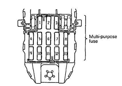
| Power supply circuit | No. | A | Load circuit | |
| Ignition switch | ACC | 1 | 15 | Windshield wiper and washer. Rear wiper and washer |
| IG1 | 2 | 10 | Meter and gauges. indicator lights. warning lights, clutch switch |
|
| ACC | 3 | 10 | Radio, clock | |
| IG2 | 4 | 10 | 4 A/T control unit. overdrive switch <4 A/T>, inhibitor switch <4 A/T>, auto-cruise control unit <4 A/T> | |
| IG1 | 5 | 10 | Back-up light. inhibitor switch <3 A/T, 4 A/T>, hazard warning light, 3 A/T control unit | |
| ACC | 6 | 10 | Horn. headlight relay, upper beam relay | |
| 7 | 15 | Cigarette lighter, remote-controlled mirror | ||
| Battery | 8 | 10 | Dome light, luggage compartment light, clock, radio, MPI control unit, 4 A/T control unit, door-ajar warning light, automatic seat belt control unit, seat belt warning buzzer, key reminder switch | |
| Ignition switch IG2 | 9 | 10 | Power window relay, defogger relay, deffoger timer, defogger switch, heater relay, blower switch, auto compressor control unit, DRL control relay, DRL control unit | |
| Battery | 10 | 20 | Heater relay | |
| 11 | 15 | Door lock relay, door lock control unit | ||
| 12 | 15 | Stop light | ||
| Ignition switch IG2 | 13 | — | — | |
Relay box in engine compartment

| Calssification | Name |
| A-01X | Alternetor relay |
| A-02X | Radiator fan motor relay |
| A-03X | Power window relay or taillight relay |
| A-04X | Headlight relay |
| A-05X | Jumper connector |
Air conditioner relay bracket
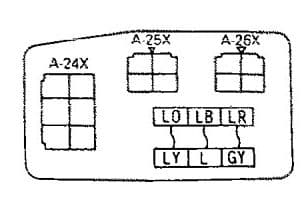
| Calssification | Name |
| A-24X | Air conditioner compressor relay |
| A-25X | Condenser fan motor |
| A-26X | Condenser fan motor relay |
Relay

| No | Circuit | Housing color | Rated capacity |
| 1 | MPI circuit | Blue | 20 |
| 2 | Headlight circuit | Green | 40 |
| 3 | Radiator fan motor circuit | Pink | 30 |
| 4 | Ignition circuit | Green | 40 |
| 5 | Alternator circuit, fusible link (6),(7),(8) circuit | Black | 80 |
| Blue | 100 | ||
| 6 | Multi-purpose fuse a power supply source | Green | 40 |
| 7 | Power window circuit | Pink | 30 |
| 8 | Defogger circuit | Pink | 30 |
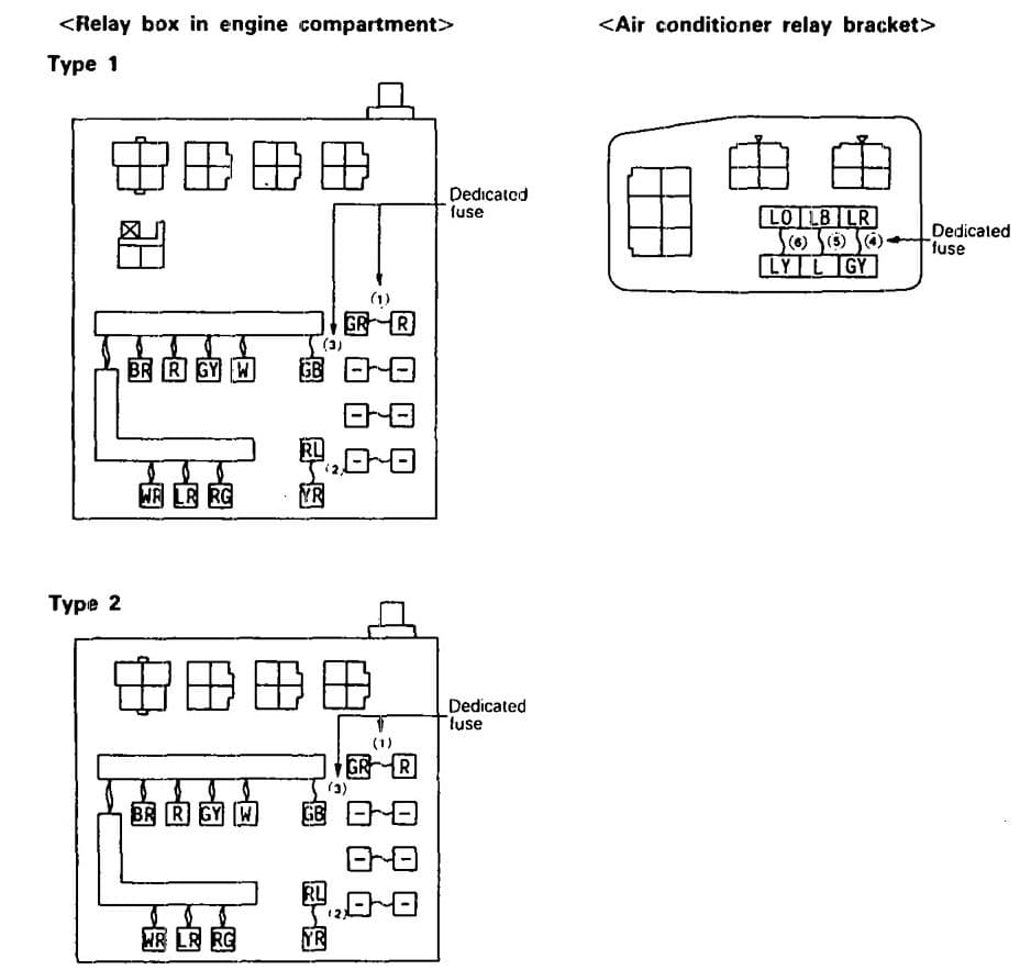
| Power supply circuit | No. | A | Housing Color | Circuit |
| Fusible link (2) | 1 | 15 | Blue | Taillight |
| Fusible link (3) | 2 | 10 | Red | Upper beam circuit |
| Battery | 3 | 10 | Red | Hazard warning light circuit |
| Fusible link (3) | 4 | 10 | Red | Air conditioner circuit |
| 5 | 25 | Transparent | ||
| 6 | 20 | Yellow |
WARNING: Terminal and harness assignments for individual connectors will vary depending on vehicle equipment level, model, and market.
Still have questions or want to supplement the article? Discuss On Telegram