In this article you will find a description of fuses and relays Eagle,
with photos of block diagrams and their locations.
Highlighted the cigarette lighter fuse (as the most popular thing people look for).
Get tips on blown fuses, replacing a fuse, and more.
Year of production: 1994, 1995, 1996
Relay box in engine compartment
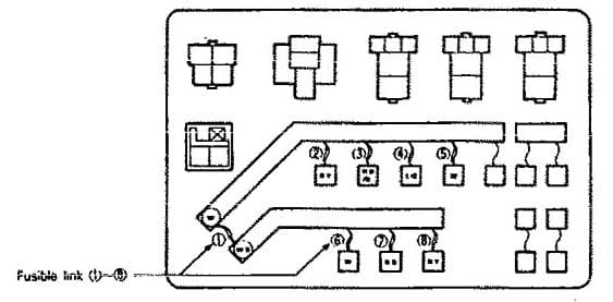
| No. | Circuit | Housing color | A |
| 1 | Fusible link No. (6), (7), (8) |
Black | 80 |
| 2 | MFI circuit | Blue | 20 |
| 3 | Headlight, taillight and generator circuit | Pink | 30 |
| 4 | Radiator fan motor, condenser fan motor and A/C compressor circuit | Pink | 30 |
| 5 | Ignition switch circuit | Green | 40 |
| 6 | Multi-purpose fuse (in the junction block) No. (1), (6), (8), (13), (14) | Green | 40 |
| 7 | Power window circuit | Pink | 30 |
| 8 | Defogger circuit | Blue | 20 |
| 9 | ABS circuit | Yellow | 60 |
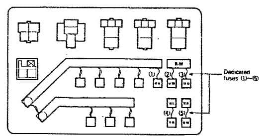
| Power supply circuit | No | A | Housing color | Circuit |
| Battery | 1 | 10 | Red | Hazard light circuit |
| Tailight relay (Battery) | 2 | 10 | Red | Tailight and illumination circuit |
| 3 | — | — | — | |
| Headlight relay (Battery) | 4 | 10 | Red | Upper beam indicator circuit |
| Battery | 5 | 10 | Red | ABS circuit |
Dedicated fuse (6) – (7) (A/C compressor clutch relay bracket in engine compartment)
| Power supply circuit | No | A | Housing color | Circuit |
| Battery | 6 | 10 | Red | A/C compressor |
| Condenser fan motor relay (Battery) | 7 | 20*1 | Yellow | Condenser fan motor circuit |
| 25*2 | ||||
| *1: 1.5L engine | ||||
| *2: 1.8L engine | ||||
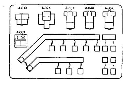
| No | Name |
| A-01X | Generator relay |
| A-02X | — |
| A-03X | Radiator fan motor relay |
| A-04X | Headlight relay |
| A-05X | Tailight relay |
| A-06X | IOD or storage connector |
Multi-Purpose Fuse Block
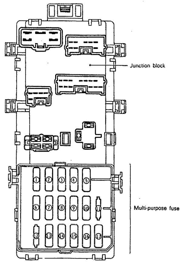
| Power supply circuit | No. | A | Housing color | Load circuit | |
| Battery | 1 | 20 | Yellow | Blower motor | |
| Ignition switch | IG1 | 2 | 10 | Red | Back-up light, buzzer assembly and combination meter <3A/T>, SRS diagnosis unit |
| 3 | 10 | Red | Combination meter, buzzer assembly and auto-cruise control main switch | ||
| ACC | 4 | 15 | Blue | Cigarette lighter and remote controlled mirror | |
| 5 | 10 | Red | Clock, radio and tape player and auto-cruise control unit | ||
| Battery | 6 | 15 | Blue | Stop light | |
| Ignition switch | IG1 | 7 | 10 | Red | Turn signal and hazard flasher unit, SRS diagnosis unit |
| Battery | 8 | 15 | Blue | Door lock control relay | |
| Ignition switch | ACC | 9 | 10 | Red | Horn |
| 10 | 15 | Blue | Wiper and washer motor | ||
| — | 11 | — | — | — | |
| Battery | 12 | — | — | — | |
| 13 | — | — | — | ||
| 14 | 10 | Red | Dome light, luggage compartment light, clock, radio and tape player, combination meter, door lock control relay, engine control module, transaxle control module | ||
| Ignition switch | IG2 | 15 | 10 | Red | Blower motor relay, defogger relay, power window relay, automatic compressor control unit, ABS power relay, ABS valve relay and DRL control unit, buzzer assembly, auto-cruise control unit and automatic seat belt control unit |
| 16 | — | — | — | ||
| 17 | 10 | Red | Cobination meter (4A/T> and transaxle control module | ||
Passenger compartment relay box
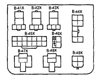
| Connector No. | Name |
| B-41X | ABS power relay |
| B-42X | Power window relay |
| B-43X | Horn relay |
| B-44X | Door lock control unit |
| B-45X | J/C (for ground circuit) |
| B-46X | — |
| B-47X | Defogger relay |
| B-48X | Starter relay |
| B-49X | — |
| — | — |
WARNING: Terminal and harness assignments for individual connectors will vary depending on vehicle equipment level, model, and market.
Still have questions or want to supplement the article? Discuss On Telegram