In this article you will find a description of fuses and relays Kia,
with photos of block diagrams and their locations.
Highlighted the cigarette lighter fuse (as the most popular thing people look for).
Get tips on blown fuses, replacing a fuse, and more.
Year of production: 2013
Instrument fuse panel
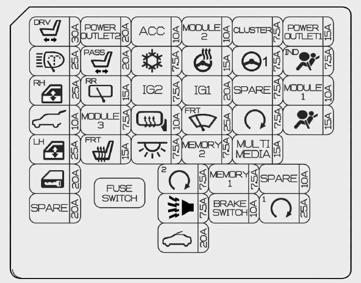
| No. | [A] | Symbol | Fuse name | Protected component |
| 1 | 30 | P/SEAT DRV | 4WAY : Driver Lumbar Support Switch 6WAY : Driver Seat Manual Switch, Driver IMS Module |
|
| 2 | 25 | H/LP WASHER | ICM Relay Box (Head Lamp Washer Relay) | |
| 3 | 25 | P/WDW RH | Power Window Relay RH, Driver/Passenger Safety Power Window Module, Rear Safety Power Window Module RH | |
| 4 | 10 | T/GATE OPEN | Tail Gate Relay | |
| 5 | 25 | P/WDW LH | Power Window Relay LH, Driver/Passenger Safety Power Window Module, Rear Safety Power Window Module LH | |
| 6 | 20 | DR LOCK | Door Lock/Unlock Relay, Dead Lock Relay | |
| 7 | 20 | SPARE | SPARE | — |
| 8 | 20 | POWER OUTLET 2 | Cigarette Lighter, Rear Power Outlet | |
| 9 | 20 | P/SEAT ASS | Passenger Lumbar Support Switch | |
| 10 | 15 | RR WIPER | ICM Relay Box (Rear Wiper Relay), Rear Wiper Motor | |
| 11 | 7,5 | MODULE 3 | Auto Light & Photo Sensor, AT lever (Shift Lock), Hazard Switch | |
| 12 | 15 | S/HEATER FRT | Driver/Passenger Seat Warmer Module | |
| 13 | 10 | ACC | ACC | A/V & Navigation Head Unit (W/O ISG), Audio (W/O ISG), DC-DC Convertor (With ISG), Digital Clock, Smart Key Control Module, BCM, Outside Mirror Switch, Outside Mirror |
| 14 | 7,5 | A/CON | Cluster Ionizer, A/C Control Module, Blower Relay, PTC Relay | |
| 15 | 7,5 | IG2 | IG2 | ICM Relay Box (Head Lamp Washer Relay), Rain Sensor, BCM, Electro Chromic Mirror, Panorama Sunroof, Smart, Key Control Module, Passenger Seat Warmer Module, Driver Seat Warmer Module |
| 16 | 10 | HTD MIRR | Driver/Passenger Outside Mirror, ECU, A/C Control Module | |
| 17 | 7,5 | INTERIOR LAMP | Glove Box Lamp, Luggage Lamp, Vanity Lamp LH/RH, Room Lamp, Overhead Console Lamp | |
| 18 | 7,5 | PDM 2 | Smart Key Control Module, Start/Stop Button Switch | |
| 19 | 7,5 | B/HORN | ICM Relay Box (Burglar Alarm Horn Relay) | |
| 20 | 20 | SUNROOF | Panorama Sunroof | |
| 21 | 10 | MODULE 2 | MODULE 2 | Electric Parking Brake Module, DC-DC Convertor (With ISG), Head Lamp Leveling Device Switch, A/C Control Module, Rear Parking Assist Sensor, Smart Parking Assist Control Module, Head Lamp LH/RH, ATM Shift Lever IND., Center Facia Switch, Crash Pad Lower Switch, river/Passenger Seat Warmer Module, Driver IMS Module |
| 22 | 15 |  |
HTD STRG | Steering Wheel Heater |
| 23 | 20 | IG1 | IG1 | E/R Fuse & Relay Box (ECU4, B/UP LAMP, ABS3, TCU2 FUSE) |
| 24 | 25 | WIPER | Wiper Relay , ICM Relay Box (Rain Sensor Relay), Front Wiper Motor | |
| 25 | 7,5 | MEMORY 2 | MEMORY 2 | Immobilizer Module (W/O Smart Key) |
| 26 | 7,5 | MEMORY 1 | MEMORY 1 | Driver/Passenger Outside Mirror (Folding), Driver/Passenger Smart Key Outside Handle, Driver IMS Module, Center Facia Switch, Instrument Cluster, Tire Pressure Monitoring Module, BCM, A/C Control Module, ICM Relay Box (Outside Mirror Folding/Unfolding Relay), Ignition Key ILL. & Door Warning Switch, Rear Parking Assist Switch, Data Link Connector, Buzzer |
| 27 | 10 | BRAKE SWITCH | Smart Key Control Module, Stop Lamp Switch | |
| 28 | 7,5 | CLUSTER | CLUSTER | Instrument Cluster, Digital Clock |
| 29 | 7,5 | POWER STEERING | EPS Unit | |
| 30 | 7,5 | SPARE | SPARE | — |
| 31 | 7,5 | START | Start Relay, ECU, Ignition Lock Switch, Transaxle Range Switch, TCU, Smart Key Control Module | |
| 32 | 15 | MULTI MEDIA | MULTI MEDIA | A/V & Navigation Head Unit (W/O ISG), Audio (W/O ISG), DC-DC Convertor (With ISG), Digital Clock |
| 33 | 10 | SPARE | SPARE | — |
| 34 | 25 | PDM1 | Smart Key Control Module | |
| 35 | 15 | POWER OUTLET1 | P/OUTLET 1 | Front Power Outlet |
| 36 | 7,5 | A/BAG IND | Instrument Cluster | |
| 37 | 10 | MODULE 1 | MODULE 1 | BCM, Tire Pressure Monitoring Module, AT Lever, Audio, Adaptive Front Lighting Module, LDWS Unit |
| 38 | 15 | A/BAG | SRS Control Module |
Engine compartment fuse panel
Gasoline engine
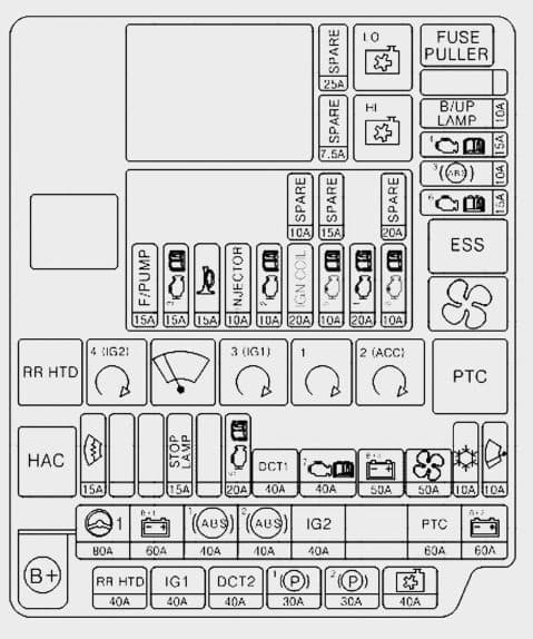
| Fuse | [A] | Symbol | Fuse name | Protected component |
| MULTI FUSE | 80 | POWER STEERING | EPS Unit | |
| 60 | B+1 | Inner Fuse Panel, IPS1 (H/LAMP HI LH,H/LAMP LOW LH, FRT TURN LH, POSITION LAMP LH), IPS2 (STATIC BENDING LAMP LH/RH, DRL LH/RH) | ||
| 40 | ABS1 | ESC Control Module, ABS Control Module | ||
| 40 | ABS2 | ESC Control Module, ABS Control Module, Multipurpose Check Connector | ||
| 40 | IG2 | IG2 | W/O Smart Key : Ignition Switch, START RELAY With Smart Key : IG2 RELAY, START RELAY |
|
| 60 | PTC | PTC | PTC Relay | |
| 60 | B+2 | Inner Fuse Panel, IPS3 (H/LAMP HI RH,H/LAMP LOW RH, FRT TURN RH,POSITION LAMP RH), IPS4 (FRT FOG LAMP LH/RH, REAR TURN LH/RH), IPS5 (REAR FOG LAMP, INT TAIL LAMP) | ||
| FUSE | 40 | RR HTD | RR HTD | RR HTD RELAY , RR HTD |
| 40 | IG1 | IG1 | W/O Smart Key : Ignition Switch With Smart Key : IG1 RELAY, ACC RELAY, INNER FUSE PANEL (FUSE No. – 8/13/21/23/28/29/35/36/37/38) |
|
| 40 | DCT2 | DCT2 | TCU (DCT) | |
| 30 | EPB1 | Electric Parking Brake Module | ||
| 30 | EPB2 | Electric Parking Brake Module | ||
| 40 | C/FAN | C/FAN LO RELAY, C/FAN HI RELAY | ||
| 15 |  |
DEICER | ICM Relay Box (Front Deicer Relay) | |
| 15 | STOP LAMP | STOP LAMP | Stop Signal Electronic Relay , HAC RELAY | |
| 20 | TCU1 | TCU | ||
| 40 | DCT1 | DCT1 | TCU (DCT) | |
| 50 | B+3 | Inner Fuse Panel (Leak Current Autocut Device, Fuse No. – 6/19/20/17/32/26/25) | ||
| 50 | BLOWER | BLOWER RELAY | ||
| 10 | A/CON | A/C Control Module | ||
| 10 | WIPER FRT | ECU, Rain Sensor | ||
| 10 | B/UP LAMP | B/UP LP | M/T : Back-up Lamp Switch, A/T : Transaxle Range Switch, TCU | |
| 15 | ECU4 | Smart Key Control Module, Immobilizer Module, ECU | ||
| 10 | ABS3 | ESC Control Module, ABS Control Module, Yaw Rate Sensor, HAC, ESS RELAY | ||
| 15 | TCU2 | Transaxle Range Switch, TCU, Stop Lamp Switch |
| Symbol | Relay name | Type |
| COOLING FAN LOW RELAY | PLUG MICRO | |
| COOLING FAN HIGH RELAY | PLUG MICRO | |
| ESS | ESS RELAY | PLUG MICRO |
| BLOWER RELAY | PLUG MICRO | |
| RR HTD | REAR DEFOGGER RELAY | PLUG MICRO |
| IG2 RELAY | PLUG MICRO | |
| FRT WIPER RELAY | PLUG MICRO | |
| IG1 RELAY | PLUG MICRO | |
| START RELAY | PLUG MICRO | |
| ACC RELAY | PLUG MICRO | |
| PTC | PTC RELAY | PLUG MINI |
| HAC | HAC RELAY | PLUG MICRO |
| [A] | Symbol | Fuse name | Relay name |
| 15 | F/PUMP | FUEL PUMP RELAY | |
| 15 | ECU3 | ECU | |
| 15 | HORN | Horn Relay | |
| 10 | INJECTOR | INJECTOR | INJECTOR, ECU, FUEL PUMP RELAY |
| 10 | ECU2 | ECU | |
| 20 | IGN COIL | IGN COIL | Ignition Coil #1/#2/#3/#4, Condenser |
| 10 | SENSOR2 | E/R Fuse & Relay Box (COOLING LOW RELAY), Oil Control Valve #1/#2 | |
| 20 | ECU1 | ECU | |
| 10 | SENSOR1 | Oxygen Sensor (UP/DOWN), Variable Intake Solenoid Valve, Purge Control Solenoid Valve |
Diesel engine
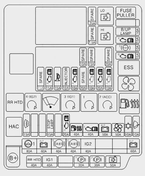
| Fuse | [A] | Symbol | Fuse name | Protected component |
| MULTI FUSE | 80 | POWER STEERING | EPS Unit | |
| 60 | B+1 | Inner Fuse Panel, IPS1 (H/LAMP HI LH,H/LAMP LOW LH, FRT TURN LH, POSITION LAMP LH), IPS2 (STATIC BENDING LAMP LH/RH, DRL LH/RH) | ||
| 40 | ABS1 | ESC Control Module, ABS Control Module | ||
| 40 | ABS2 | ESC Control Module, ABS Control Module, Multipurpose Check Connector | ||
| 40 | IG2 | IG2 | W/O Smart Key : Ignition Switch, START RELAY With Smart Key : IG2 RELAY, START RELAY |
|
| 60 | B+2 | Inner Fuse Panel, IPS3 (H/LAMP HI RH,H/LAMP LOW RH, FRT TURN RH,POSITION LAMP RH), IPS4 (FRT FOG LAMP LH/RH, REAR TURN LH/RH), IPS5 (REAR FOG LAMP, INT TAIL LAMP) | ||
| FUSE | 40 | RR HTD | RR HTD | RR HTD RELAY , RR HTD |
| 40 | IG1 | IG1 | W/O Smart Key : Ignition Switch With Smart Key : IG1 RELAY, ACC RELAY, INNER FUSE PANEL (Fuse No. – 38/36/21/37/23/29/28, Fuse No. – 13/8/35) |
|
| 30 | EPB1 | Electric Parking Brake Module | ||
| 30 | EPB2 | Electric Parking Brake Module | ||
| 50 | C/FAN | C/FAN LO RELAY, C/FAN HI RELAY | ||
| 15 | |
DEICER | ICM Relay Box (Front Deicer Relay) | |
| 15 | STOP LAMP | STOP LAMP | Stop Signal Electronic Relay , HAC RELAY | |
| 20 | TCU1 | TCU | ||
| 40 | FUEL HEATER | FUEL HEATER RELAY | ||
| 40 | EMS | EMS BOX (Fuse No. – 1/2/3/4/5/6/7/8/9) | ||
| 50 | B+3 | Inner Fuse Panel (Leak Current Autocut Device, Fuse No. – 6/19/20/17/32/26/25) | ||
| 50 | BLOWER | BLOWER RELAY | ||
| 10 | A/CON | A/C Control Module | ||
| 10 | WIPER FRT | ECU, Rain Sensor | ||
| 10 | B/UP LAMP | B/UP LP | M/T : Back-up Lamp Switch, A/T : Transaxle Range Switch, TCU | |
| 15 | ECU4 | Smart Key Control Module, Immobilizer Module, ECU | ||
| 10 | ABS3 | ESC Control Module, ABS Control Module, Yaw Rate Sensor, HAC, ESS RELAY | ||
| 15 | TCU2 | Transaxle Range Switch, TCU |
| Symbol | Relay name | Type |
| COOLING FAN LOW RELAY | PLUG MICRO | |
| COOLING FAN HIGH RELAY | PLUG MICRO | |
| ESS | ESS RELAY | PLUG MICRO |
| BLOWER RELAY | PLUG MICRO | |
| RR HTD | REAR DEFOGGER RELAY | PLUG MICRO |
| IG2 RELAY | PLUG MICRO | |
| FRT WIPER RELAY | PLUG MICRO | |
| IG1 RELAY | PLUG MICRO | |
| START RELAY | PLUG MICRO | |
| ACC RELAY | PLUG MICRO | |
| FUEL HEATER RELAY | PLUG MINI | |
| HAC | HAC RELAY | PLUG MICRO |
| [A] | Symbol | Fuse name | Relay name |
| 15 | SPARE | SPARE | — |
| 15 | HORN | Horn Relay | |
| 10 | ECU2 | ECU | |
| 20 | SPARE | SPARE | — |
| 10 | SENSOR2 | E/R Fuse & Relay Box (COOLING FAN LOW RELAY), Lambda Sensor (D4FB), Stop Lamp Switch | |
| 20 | ECU1 | ECU | |
| 10 | SENSOR1 | DSL Box (PTC1 RELAY, GLOW RELAY), VGT Control Sensor, Camshaft Position Sensor, Electrical EGR Valve |
Multi fuse box (diesel)
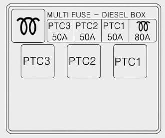
| Description | [A] | Protrcted component |
| 80 | Glow Relay | |
| PTC 1 | 50 | PTC 1 Relay |
| PTC 2 | 50 | PTC 2 Relay |
| PTC 3 | 50 | PTC 3 Relay |
WARNING: Terminal and harness assignments for individual connectors will vary depending on vehicle equipment level, model, and market.
Still have questions or want to supplement the article? Discuss On Telegram