Year of production: 1995, 1996, 1997, 1998, 1999, 2000, 2001, 2002
Importing this car? Don't forget to calcular iva 23%.
Front power distribution box

| No. |
A |
Circuit |
| 1 | — | — |
| 2 | — | — |
| 3 | — | — |
| 4 | — | — |
| 5 | 5 | ’95-’99: Horn relay |
| 15 | ’99-’02: Horn relay | |
| 6 | 5 | Make-up mirror light, driver’s side Make-up mirror light, passenger’s side Convertible soft top control unit |
| 7 | 5 | Radio control unit Aerial amplifier AM/FM (with remote control central locking) On-board monitor control unit Spatial sound switch Interface Navigation computer GPS receiver Transceiver/charging electronics Pushbutton, convertible soft top closed Basic interface telephone Voice input Diversity Eject box Telematics control unit (TCU-Everest) Universal electronic charging and hands-free module (ULF) |
| 8 | 5 | Sequential mechanical gear |
| 9 | 5 | General module control unit Light switching centre control unit Cruise control module Brake light switch Volute spring Clutch switch module |
| 10 | 5 | Instrument cluster control unit |
| 11 | 5 | Sensor for LH side airbag (satellite) Sensor for RH side airbag (satellite) Multiple restraint system control unit Hall sensor, driver’s seat belt buckle Hall sensor, passenger’s seat belt buckle Electronic seat control |
| 12 | 7,5 | Switch center |
| 13 | 7,5 | Rollover sensor |
| 14 | 5 | Electronic immobiliser control unit Gearshift lock |
| 15 | 5 | Rain sensor Intermittent wipe/wash control unit, rear |
| 16 | — | — |
| 17 | 30 | General module control unit |
| 18 | 20 | Cigarette lighter |
| 19 | — | — |
| 20 | — | — |
| 21 | — | — |
| 22 | 15 | ’95-’99: Sequential mechanical gear box |
| 25 | ’99-’02: Sequential mechanical gear box Compensator Switch center |
|
| 23 | 25 | Auxiliary water pump |
| 24 | 10 | Electrochromic interior rear-view mirror Park distance control unit (PDC) |
| 25 | 15 | Outside mirror, passenger’s side Thermal switch, heated spray nozzles |
| 26 | 15 | Garage door opener |
| 27 | 10 | Reversing light relay Gear position switch Transmission control unit |
| 28 | 5 | Heating and A/C control module Heating blower relay Relay, A/C compressor Dual-function switch recirculated air/rear window defogger Temperature switch Rear window defogger relay (convertible) |
| 29 | 20 | Digital motor electronics control unit Unloader relay terminal 15 Digital diesel electronics control unit Transmission control unit |
| 30 | 7,5 | Oil level sensor Alternator Temperature switch Transmission control unit Data link connector |
| 31 | 5 | Mirror adjustment switch |
| 32 | 5 | Light switching centre control uni Xenon headlight, left Xenon headlight, right Control unit for adaptive headlight () |
| 33 | 5 | ASC/DSC button ABS/DSC unit (with DSC) Switch center |
| 34 | 5 | Instrument cluster control unit Fuel pump control (EKPS) |
| 35 | 50 | ABS/DSC unit Relay, convertible top drive |
| 36 | 50 | Secondary air pump relay |
| 37 | 50 | Heating blower relay Blower switch (with IHS) Blower output stage (with IHKA) Electric fan |
| 38 | 10 | ’95-’99: Fog light relay |
| 15 | ’99-’02: Fog light relay | |
| 39 | 5 | Transceiver/charging electronics |
| 10 | Voice input Basic interface telephone Eject box Compensator Transceiver/charging electronics Interface Telematics control unit (TCU-Everest) Aerial splitter |
|
| 40 | 5 | Steering angle sensor, DSC |
| 41 | 30 | On-board monitor control unit Amplifier Radio control unit CD changer Subwoofer box Navigation computer Video module control unit Switch center |
| 42 | 30 | Switch center |
| 43 | 5 | Instrument cluster control unit Data link connector |
| 44 | 20 | Amplifier |
| 45 | 20 | Intermittent wipe/wash control unit, rear |
| 46 | 20 | Convertible soft top control unit Sunroof module control unit Relay, convertible top 1 |
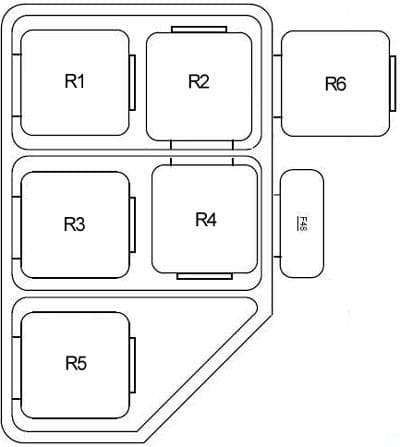
| Relay | ||
| R1 | Fuel pump relay | |
| R2 | Engine control module | |
| R3 | Wiper motor relay | |
| R4 | Horn relay | |
| R5 | Fog light relay | |
| R6 | High beam relay | |
| R7 | High beam relay | |
| R8 | Hazard flasher relay | |
| R9 | Blower relay | |
| R10 | Rear defogger relay | |
| R11 | ABS relay | |
| R12 | ABS pump motor relay | |
| R13 | Auxiliary fan stage 2 relay (high speed) | |
| R14 | A/C compressor relay | |
| R15 | Auxiliary fan stage 1 relay (low speed) | |
Relay carrier under LH side of dash
| No. |
A |
Circuit |
| 48 | 40 | A/C compressor |
| 50 | 5 | Security horn |
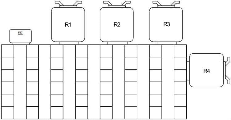
| Relay | ||
| R1 | Independent ventilation relay | |
| R2 | Twin relay | |
| R3 | Crash alarm sensor | |
| R4 | Day running ligth relay | |
| R5 | Folding sunroof comfort relay | |
| R6 | Unloader relay terminal R | |
Connector strip under LH side of dash
| No. |
A |
Circuit |
| 47 | 15 | Horn relay On-board computer |
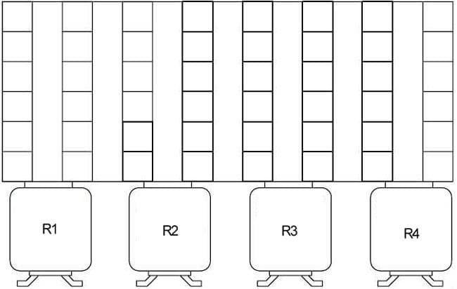
| Relay | ||
| R1 | Unloader relay terminal 30 | |
| R2 | Rear lights relay | |
| R3 | Wiper motor relay | |
| R4 | Starter immobilization relay | |
Connector strip under RH side of dash
| No. | Relay |
| R1 | Front fog light relay |
| R2 | Parking light relay |
| R3 | Door lock heating relay |
| R4 | Rear window blower relay |
Auxiliary fuse box in luggage compartment
| No. |
A |
Circuit |
| 49 | 50 | Convertible soft top module |
Auxiliary relay box
| No. |
A |
Circuit |
| 111 | 25 | Hydraulic pump relay |
| 222 | 5 | SMG control unit |
WARNING: Terminal and harness assignments for individual connectors will vary depending on vehicle equipment level, model, and market.