Year of production: 2014, 2015, 2016, 2017, 2018
Importing this car? Don't forget to calcular iva 23%.
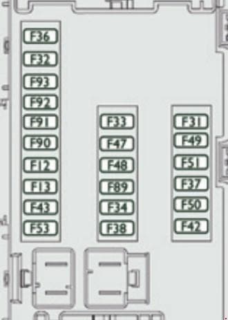
Dashboard, left-hand side, fuses
| No. |
A |
Allocation |
| 12 | 7.5 | Right-hand dipped headlamp |
| 13 | 7.5 | Left-hand dipped headlamp |
| 31 | 5 | Engine compartment control unit relay – Dashboard control unit relay (ignition switch +) |
| 32 | 7.5 | Cabin lighting (battery +) |
| 33 | 7.5 | Battery check sensor on Stop & Start version (battery +) |
| 34 | 7.5 | Minibus interior lighting – Hazard warning lamps |
| 36 | 10 | Audio system – Air conditioning controls – Alarm – Tachograph – Battery cut-off control unit – Additional heating programmer (battery +) |
| 37 | 7.5 | Brake lamp switch – Third brake lamp – Instrument panel (ignition +) |
| 38 | 20 | Central door locking (battery +) |
| 42 | 5 | ABS control unit and sensor – ASR sensor – DSC sensor – Brake lamp switch |
| 43 | 20 | Windscreen wiper motor (ignition switch +) |
| 47 | 20 | Driver’s electric window motor |
| 48 | 20 | Passenger’s electric window motor |
| 49 | 5 | Parking sensors control unit – Audio system – Steering mounted controls – Centre and side switch panels -Auxiliary switch panel – Battery cut-off control unit (ignition switch +) |
| 50 | 7.5 | Airbags and pre-tensioners control unit |
| 51 | 5 | Tachograph – Power steering control unit – Air conditioning – Reversing lamps – Water in Diesel sensor -Air flow sensor (ignition switch +) |
| 53 | 7.5 | Instrument panel (battery +) |
| 89 | – | Not used |
| 90 | 7.5 | Left-hand main beam |
| 91 | 7.5 | Right-hand main beam |
| 92 | 7.5 | Left-hand front foglamp |
| 93 | 7.5 | Right-hand front foglamp |
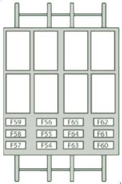
Door pillar, right-hand side, fuses
| No. |
A |
Allocation |
| 54 | – | Not used |
| 55 | 15 | Heated seats |
| 56 | 15 | Rear passenger 12V socket |
| 57 | 10 | Under seat additional heating |
| 58 | 15 | Heated rear screen, left-hand |
| 59 | 15 | Heated rear screen, right-hand |
| 60 | – | Not used |
| 61 | – | Not used |
| 62 | – | Not used |
| 63 | 10 | Rear passenger additional control |
| 64 | – | Not used |
| 65 | 30 | Rear passenger additional heating fan |
Fuses in the engine compartment

| No. |
A |
Allocation |
| 1 | 40 | ABS pump supply |
| 2 | 50 | Diesel pre-heat unit |
| 3 | 30 | Ignition switch – Starter motor |
| 4 | 40 | Fuel heater |
| 5 | 20/50 | Cabin ventilation with additional programmable heating (battery +) |
| 6 | 40/60 | Cabin fan maximum speed (battery +) |
| 7 | 40/50/60 | Cabin fan minimum speed (battery +) |
| 8 | 40 | Cabin fan assembly (ignition switch +) |
| 9 | 15 | Rear 12 V socket (battery +) |
| 10 | 15 | Horn |
| 11 | – | Not used |
| 14 | 15 | Front 12 V socket (battery +) |
| 15 | 15 | Cigarette lighter (battery +) |
| 16 | – | Not used |
| 17 | – | Not used |
| 18 | 7.5 | Engine management control unit (battery +) |
| 19 | 7.5 | Air conditioning compressor |
| 20 | 30 | Screenwash/headlamp wash pump |
| 21 | 15 | Fuel pump supply |
| 22 | – | Not used |
| 23 | 30 | ABS electrovalves |
| 24 | 7.5 | Auxiliary switch panel – Door mirror controls and folding (ignition switch +) |
| 30 | 15 | Door mirror heating |
WARNING: Terminal and harness assignments for individual connectors will vary depending on vehicle equipment level, model, and market.