Year of production: 2002, 2003, 2004, 2005, 2006
Importing this car? Don't forget to calcular iva 23%.
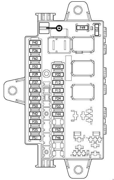
Main fusebox under the dashboard on driver’s side for LH drive versions, on passenger’s side for RH drive versions
| No. |
A |
Function |
| 12 | 5 | Front right-hand side light – Rear right-hand side light |
| 13 | 5 | Front left-hand side light – Rear left-hand side light |
| 24 | 5 | Control lights – Side/taillight warning light – Number plate lights |
| 25 | 7.5 | Radio |
| 26 | 7.5 | Brake lights |
| 27 | 7.5 | Alarm – Remote control – Chronotachograph – Phone – Cruise control – Power mirrors |
| 31 | 10 | Ignition switch |
| 32 | 15 | Radio |
| 33 | 7.5 | Rear fog lights |
| 35 | 7.5 | Door power window control – ABI |
| 37 | 10 | PCC – Instrument panel |
| 39 | 10 | EOBD diagnostic socket – Cab lights |
| 42 | 7.5 | ABS control unit |
| 43 | 15 | Windscreen washer pump |
| 44 | 15 | Cigar lighter |
| 49 | 15 | Headlight washer pump |
| 50 | 7.5 | Airbag control unit |
| 51 | 10 | PCA (Ambulance – Minibus versions) |
| 52 | 20 | Front current socket |
| 53 | 10 | Instrument panel – Hazard lights – Direction indicators |
| 55 | 30 | Cab fan (with Webasto system) – Webasto control unit – Cab fan (with climate control) – Cab heater fan |
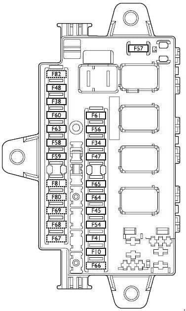
Fusebox under the dashboard on passenger’s side for LH drive versions, on driver’s side for RH drive versions
| No. |
A |
Function |
| 34 | 10 | Chronotachograph – Phone – Alarm – Remote control |
| 38 | 20 | ABI for door lock |
| 40 | 15 | Right heated rear window |
| 41 | 10 | Door mirror defrosting device |
| 45 | 15 | Driver’s seat warmer |
| 47 | 20 | ABI for left power window |
| 48 | 20 | ABI for right power window |
| 54 | 15 | Left heated rear window |
| 56 | 30 | Additional climate control |
| 57 | 15 | Additional heater fan |
| 58 | 5 | Webasto timer |
| 59 | 15 | Food box power |
| 60 | 10 | Alarm blinker |
| 61 | 20 | Webasto unit |
| 63 | 30 | Rotating lights (Ambulance versions) |
| 64 | 20 | Rear current socket – Siren (Ambulance versions) – Suction fan (Minibus versions) |
| 65 | 10 | Current socket for special set-up |
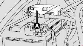
Battery fusebox
| No. |
A |
Function |
| 70 | 150 | CVM protection |
| 71 | 80 | CFO protection |
| 72 | 125 | Alternator |
| 72 | 70 | Alternator (2.0 – 2.0 JTD with heating system) |
| 72 | 100 | Alternator (2.8 JTD with heating system – 2.0 JTD with climate control system) |
| 73 | 70 | Body-builders’ current socket |
Engine compartment fusebox
| No. |
A |
Function |
| 1 | 60 | CFB protection |
| 2 | 50 | Glow plug preheating |
| 3 | 30 | Ignition switch |
| 4 | 50 | ABS control unit |
| 5 | 30 | Cab fan (climate control) |
| 6 | 40 | Radiator fan low-speed resistor (2.0 with climate control system) Engine control unit (2.0 with climate control system) Engine cooling fan (2.0 with climate control system) Engine control unit (2.0 with climate control system) |
| 6 | 40 | Engine cooling fan 1st speed Engine control unit 1st speed |
| 7 | 40 | Engine cooling fan (2.0 with climate control system) Engine control unit (2.0 with climate control system) |
| 7 | 40/60 | Engine cooling fan 2nd speed Engine control unit 2nd speed Radiator fan 2nd speed remote switch coil (climate control) |
| 8 | 30 | Windscreen wiper motor – Windscreen washer pump |
| 9 | 15 | Front fog lights |
| 10 | 15 | Horn – Steering column stalk control |
| 11 | 10 | E.I. secondary services – Engine control unit |
| 14 | 10 | Right-hand dipped beam headlight |
| 15 | 10 | Left-hand dipped beam headlight |
| 16 | 7.5 | E.I. system – Fiat code |
| 17 | 5 | E.I. primary services – Engine control unit |
| 18 | 7.5 | Fiat code – Engine control unit |
| 19 | 7.5 | Compressor |
| 20 | 30 | PTC |
| 21 | 15 | Fuel pump |
| 22 | 20 | E.I. primary services |
| 23 | 10 | Automatic gearbox control unit |
| 24 | 15 | Automatic gearbox control unit |
| 30 | 15 | Main beam headlights |
WARNING: Terminal and harness assignments for individual connectors will vary depending on vehicle equipment level, model, and market.


