Year of production: 2001, 2002, 2003, 2004, 2005, 2006, 2007
Importing this car? Don't forget to calcular iva 23%.
Passenger compartment fuse panel (2001-2004)
The fuse panel is located on the left hand side kick panel.
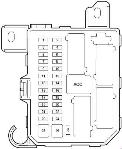
| No. | A | Protected components |
| 1 | 5 | Canister vent control solenoid |
| 2 | 5 | Blower relay (coil), Pressure switch to PCM, Blower Relay (coil), Rear Defrost Relay (coil; up to 2002) |
| 3 | 10 | Rear wiper motor, Rear washer motor, Rear wiper relay (coil) |
| 4 | 10 | Four-wheel drive control module, Cluster (restraints control warning) |
| 5 | 5 | ABS unit (EVAC & FILL), ASC unit, Restraints Control Module (RCM), ASC main SW to ASC unit, Clock spring switch (as of 2003) |
| 6 | 10 | Flasher unit, Reversing lamps, Park Aid Module (PAM; as of 2003) |
| 7 | 10 | Passive Anti-theft Transceiver (PATS), Restraints Control Module, EEC fuse (as of 2003) |
| 8 | 10 | Cluster, Shift lock relay (coil), O/D signal to PCM, GEM (as of 2003), E/C autolamp mirror (as of 2003) |
| 9 | 3 | PCM relay (coil), Fan relay 1, 2, 3 (coil), A/C relay (coil) |
| 10 | 20 | Front wiper motor, Front washer motor |
| 11 | 10 | ACC relay (coil), Key interlock solenoid, GEM, IGN Relay (coil; up to 2002), Starter Relay (coil; up to 2002) |
| 12 | 5 | Radio, Clock (up to 2002) |
| 13 | — | — |
| 14 | 20 | Cigar lighter |
| 15 | 15 | Park lamp relay, Front position lamps, License lamps, Tail lamps, Park lamp relay (coil), Trailer fuse, Illumination fuse |
| 16 | 10 | Cluster, Power mirror, GEM, Heated seats (as of 2003) |
| 17 | 15 | Sun roof motor |
| 18 | 5 | Illumination for: Cluster, Heater unit, Radio, Hazard switch, Rear defrost switch, 4WD switch, Front fog switch |
| 19 | 10 | Subwoofer amp |
| 20 | 15 | Turn Indicators, Front Side Turn Lamps, Front turn lamps, Rear turn lamps, Trailer turn, Flasher unit |
| 21 | 10 | Trailer position lamps |
| 22 | 15 | — |
| 23 | 20 | as of 2002: Horn relay |
| 15 | up to 2001: Horn | |
| 24 | 15 | Stoplamps, High mounted stoplamp, Trailer stoplamp, ABS unit, ASC unit (Brake Pedal Position Switch), PCM, Shift solenoid |
| 25 | 30 | Power window motors |
| 26 | 30 | Power door lock motors, GEM (door lock relay coil), Power seat, 4WD relay (as of 2003) |
| 27 | 10 | GEM, Audio, Cluster, Interior lamp, Map lamp, Cargo lamp, Datalink connector (as of 2003) |
| Relay | ||
| ACC | Accessory relay | |
Passenger compartment fuse panel (2005-2007)
The fuse panel is located on the right-hand side of the center console, by the instrument panel.
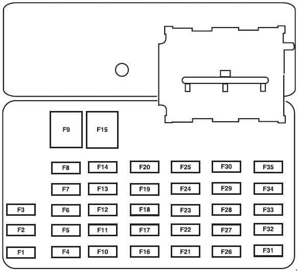
| No | A | Protected components |
| 1 | 15 | Trailer tow park lamps |
| 2 | — | — |
| 3 | 15 | Front and rear park lamps |
| 4 | 10 | Ignition switch |
| 5 | 2 | Powertrain Control Module (PCM relay), Fuel pump relay, Main fan relay, High/Low speed fan relay 2, PATS module |
| 6 | 15 | Center High-Mounted Stop Lamp (CHMSL), Stop lamps, PCM, Anti-lock Brake System (ABS), Speed control, Brake On-Off switch |
| 7 | 10 | Instrument cluster, Diagnostic connector, Power mirror switch, Radio |
| 8 | 5 | as of 2007: Canister vent |
| 9 | 30 | Power door locks, Power seats |
| 10 | 15 | Heated mirrors |
| 11 | 15 | Sunroof, Electrochromatic mirror |
| 12 | 5 | Radio |
| 13 | — | — |
| 14 | — | — |
| 15 | 30 | Power windows |
| 16 | 15 | Subwoofer |
| 17 | 15 | Low beams |
| 18 | 10 | 4WD |
| 19 | — | — |
| 20 | 15 | Horn |
| 21 | 10 | up to 2006: Rear wiper motor, Rear wiper washer |
| 15 | as of 2007: Rear wiper motor, Rear wiper washer | |
| 22 | 10 | Instrument cluster |
| 23 | — | — |
| 24 | 20 | Cigar lighter |
| 25 | 20 | Front wiper motor, Front wiper washer |
| 26 | 5 | Climate control system mode switch |
| 27 | 5 | Canister vent (up to 2006), Speed control cancel switch |
| 28 | 10 | Instrument cluster |
| 29 | 10 | Reverse park aid |
| 30 | — | — |
| 31 | — | — |
| 32 | 10 | Brake-Transmission shift lock |
| 33 | 15 | Air bag module, Passenger Air bag Deactivation (PAD) indicator lamp, Occupant Classification Sensor (OCS) |
| 34 | 5 | ABS module, Evac and Fill, Speed control |
| 35 | 5 | Heated seats module, 4WD |
Engine Compartment Fuse Box (2001-2004)
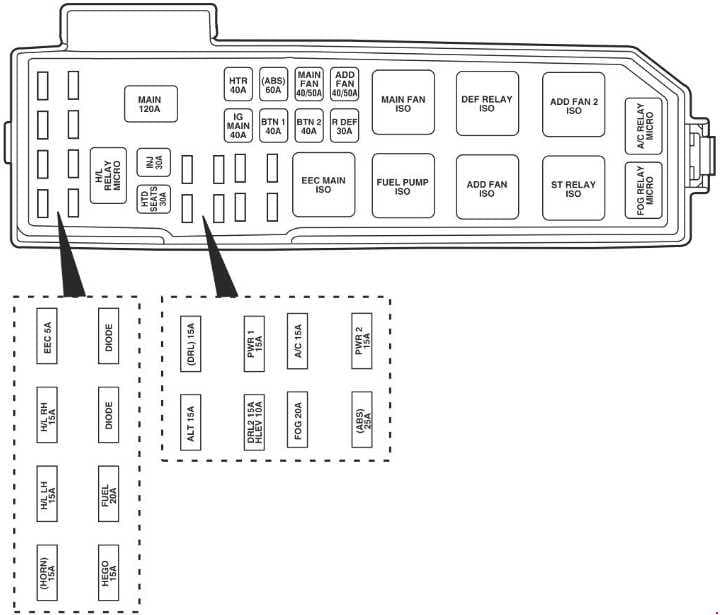
| Fuse | A | Protected components |
| Horn | 15 | Horn |
| H/L LH | 15 | Headlamp (high/low left, High beams) |
| H/L RH | 15 | Headlamp (high/low right, High beams) |
| EEC | 5 | EEC (KPWR) |
| HE GO | 15 | HEGO 1,2, CMS 1,2, VMV |
| FUEL | 20 | Fuel pump, EEC (FPM) |
| HTD SEATS | 30 | Heated seats (if equipped) |
| INJ | 30 | EEC (VPWR), EVR, MAF, I AC, Bulkhead, HEGO fuse (as of 2003) |
| MAIN | 120 | Main |
| ALT | 15 | Alternator/ Regulator |
| DRL | 15 | Daytime Running Lamps (DRL) unit (feed), DRL relay |
| DRL2 | 15 | DRL module |
| HLEV | 10 | DHLEV |
| PWR 1 | 15 | Auxiliary power point |
| FOG | 20 | Foglamps, Foglamp indicator |
| A/C | 15 | A/C clutch |
| ABS | 25 | Auxiliary power point |
| IG MAIN | 40 | Starter |
| HTR | 40 | Blower motor, Blower motor relay |
| BTN 1 | 40 | JB – Accessory relay, Radio, TNS relay, Cigar lighter, Cluster, Power mirror, GEM, Accessory delay relay (as of 2003), Power windows (as of 2003), Power moonroof (as of 2003), Clock (up to 2002) |
| (ABS) | 60 | ABS motor, EVAC & FILL (as of 2003) |
| BTN 2 | 40 | JB – Radio, CD changer, Cluster, Dome lamps, Map lamps, Cargo lamps, Horn relay (as of 2003), GEM, Power locks (as of 2003), Speed control (as of 2003) |
| MAIN FAN | 40(2.0L) | Main fan |
| 50(3.0L | ||
| RDEF | 30 | Rear defroster |
| ADD FAN | 40(2.0L) | Add fan |
| 50(3.0L) | ||
| Relay | ||
| EEC MAIN ISO | EEC relay | |
| FUEL PUMP ISO | Fuel pump relay | |
| MAIN FAN ISO | Low-speed fan control relay (2.0L engine) High-speed fan control relay I (3.0L engine) |
|
| ADD FAN ISO | High-speed fan control relay 1 (2.0L engine) Low-speed fan control relay (3.0L engine) |
|
| DEF RELAY ISO | Rear defroster relay | |
| ST RELAY ISO | Starter relay | |
| ADD FAN 2 ISO | High-speed fan control relay 2 (3.0L engine) Medium-speed fan control relay (2.0L engine) |
|
| FOG RELAY MICRO | Foglamp relay | |
| A/C RELAY MICRO | A/C clutch relay | |
| H/L RELAY MICRO | Headlamp (high/low, right/left relay) | |
| Diode | ||
| DIODE | — | |
| DIODE | — | |
Engine Compartment Fuse Box (2005-2007)
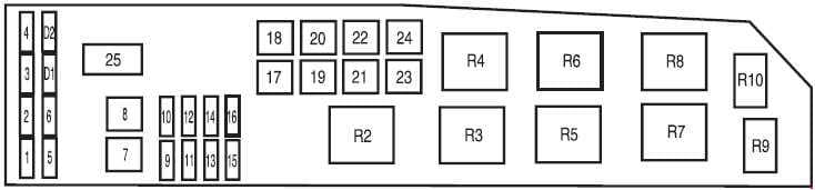
| No. | A | Protected components |
| 1 | — | — |
| 2 | 25 | Headlamp power |
| 3 | 25 | High beams, Turn signals, Interior lamps, Headlamp power |
| 4 | 5 | Keep Alive Power (KA PWR) |
| 5 | 15 | Heated Exhaust Gas Oxygen (HEGO) sensors |
| 6 | 20 | Fuel pump |
| 7 | 40 | RUN/ACC relay -Electrochromatic mirror, Cigar lighter, Front and rear wipers |
| 8 | 30 | Powertrain Control Module (PCM), Injectors and coil |
| 9 | 15 | Alternator |
| 10 | 30 | Heated seats |
| 11 | 10 | PCM |
| 12 | 20 | Power point |
| 13 | 20 | Fog lamps |
| 14 | 15 | A/C clutch, A/C relay |
| 15 | 30 | Anti-lock Brake System (ABS) solenoid |
| 16 | 25 | I/P fuse panel (RUN/START) |
| 17 | 50 | Ignition (main) |
| 18 | 40 | Blower motor |
| 19 | 40 | Accessory delay relay – Subwoofer and 4WD, Low beam |
| 20 | 60 | ABS |
| 21 | 40 | Horn, CHMSL, Cluster, Power locks and power seats |
| 22 | 40 (I4) | Cooling fan |
| 50 (V6) | ||
| 23 | 40 | Rear defroster, Park lamps relay |
| 24 | 40 (I4) | High/Low speed fan |
| 50 (V6) | ||
| 25 | — | Shunt |
| Relay | ||
| R2 | PCM relay | |
| R3 | Fuel pump relay | |
| R4 | Cooling fan relay | |
| R5 | High/Low speed fan relay 1 | |
| R6 | Blower motor relay | |
| R7 | Starter relay | |
| R8 | High/Low speed fan relay 2 | |
| R9 | Fog lamps relay | |
| R10 | A/C relay | |
| Diode | ||
| D1 | — | |
| D2 | A/C diode | |
WARNING: Terminal and harness assignments for individual connectors will vary depending on vehicle equipment level, model, and market.