Year of production: 2011, 2012, 2013, 2014, 2015
Importing this car? Don't forget to calcular iva 23%.
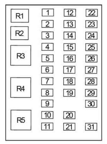
Passenger Compartment Fuse Box
| Number | Ampere rating [A] | Description |
| 1 | 20 | Horn |
| 2 | 15 | Flasher relay |
| 3 | 20 | Power point |
| 4 | 10 | Data Link Connector (DLC), Engine diagnostic connector, Parking brake warning |
| 5 | 15 | Run relay |
| 6 | — | — |
| 7 | — | — |
| 8 | 5 | Radio, GEM |
| 9 | 5 | Power window relay |
| 10 | 15 | Heated mirrors |
| 11 | 5 | Wiper and washer systems |
| 12 | 10 | Transmission shift selector |
| 13 | 20 | Radio/SYNC®, Power mirrors |
| 14 | 10 | Interior lamp relay |
| 15 | 10 | Interior lamp relay |
| 16 | 15 | High beams, Indicator |
| 17 | — | — |
| 18 | 5 | Dimmer switch, Interior lighting |
| 19 | 15 | Engine control |
| 20 | 5 | Starting system |
| 21 | 10 | DRL resistor |
| 22 | 15 | Air horn, Air suspension dump, Two-speed axle, Driver-controlled locking differential |
| 23 | 10 | Flasher relay |
| 24 | 15 | ABS relay, Fuel heater relay, Air dryer |
| 25 | 10 | Blower motor relay |
| 26 | 10 | Right-hand low beam headlight |
| 27 | — | — |
| 28 | 10 | Left-hand low beam headlight |
| 29 | 10 | Cluster, GEM |
| 30 | 15 | Allison electronic transmission |
| 31 | 15 | Mirror fold relay |
| Relay | ||
| R1 | Interior lamps | |
| R2 | — | |
| R3 | Horn | |
| R4 | — | |
| R5 | — | |
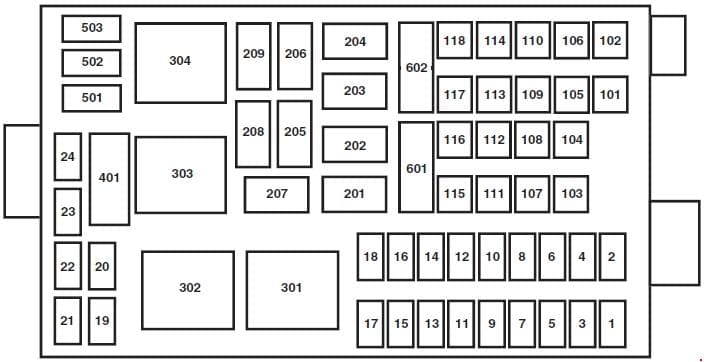
Engine Compartment Fuse Box
| Number | Ampere rating [A] | Description |
| 1 | 20 | Upfitter switches (AUX 2 and AUX 4)/Trailer 12V socket pin |
| 2 | 30 | Power seat (driver) |
| 3 | 30 | Power seat (passenger) |
| 4 | 15 | Windshield washer relay, Washer pump motor |
| 5 | 5 | Brake warning switch (hydraulic brake vehicles only) |
| 6 | 20 | Upfitter switches (AUX 1 and AUX 3) |
| 7 | 15 | Brake pressure switches, ABS event relay |
| 8 | 20 | Diesel: DEF (Urea), Line heaters |
| 9 | 20 | Ignition switch, Starter cutoff |
| 10 | 15 | Air tank moisture removal valve |
| 11 | 30 | Electric trailer brake |
| 12 | 20 | Passenger compartment fuse box 5 and 21 |
| 13 | 15 | Instrument cluster/Gateway module |
| 14 | 20 | Diesel: Nitrogen oxide sensor |
| 15 | — | — |
| 16 | 5 | Bendix® Air ABS |
| 17 | — | — |
| 18 | 10 | Fuel transfer pump |
| 19 | 15 | Gasoline: Powertrain control module power 1 |
| 20 | 10 | Gasoline: Powertrain control module power 2 |
| 21 | 20 | Gasoline: Powertrain control module power 3 |
| 22 | 20 | Gasoline: Powertrain control module power 4 |
| 23 | — | — |
| 24 | — | — |
| 101 | 30 | Bendix Air ABS relay (Air brake vehicles only) |
| Hydraulic brakes module (Hydraulic brake vehicles only) | ||
| 102 | 20 | Ignition switch |
| 103 | 20 | Ignition switch, Passenger compartment fuse box fuses 19, 29 and 30 |
| 104 | 20 | Power point |
| 105 | 20 | Power door lock switches |
| 106 | 30 | Main light switch, Multi-function switch |
| 107 | 50 | Passenger compartment fuse box fuses 1, 2, 3, 4, 12, 13, 14 and 15 |
| 108 | 40 | Diesel: Fuel heater |
| 20 | Gasoline: Fuel pump module | |
| 109 | 40 | Power window |
| 110 | 30 | Windshield wiper |
| 111 | 30 | Body builder relay, Parking lamps |
| 112 | 40 | Blower motor |
| 113 | 30 | Heated seats, Air-Ride seat |
| 114 | 20 | Aftertreatment DCU |
| 115 | 20 | Ignition switch, Passenger compartment fuse box fuses 8, 9, 10 and 11 |
| 116 | 30 | Left/Right turn relays, Back-up lamp relay |
| 117 | 20 | Stoplamps |
| 118 | 60 | Hydraulic brake vehicles (Trailer tow package only) |
| 601 | 60 | Trailer socket |
| 602 | 60 | Air brake trailer tow fuse block |
| 30 | Hydraulic brakes pump motor 2 | |
| Relay | ||
| 201 | Windshield washer relay | |
| 202 | Wiper high/low relay | |
| 203 | Wiper run/park relay | |
| 204 | Windshield wiper relay | |
| 205 | Body builder relay, right turn | |
| 206 | Body builder relay, left turn | |
| 207 | ABS event relay (Hydraulic brake vehicles only) | |
| 208 | Body builder relay, back-up lamps relay | |
| 209 | Auxiliary stoplamp relay | |
| 301 | Diesel: Fuel heater/Fuel transfer pump relay Gasoline: Fuel pump module |
|
| 302 | Body builder relay, parking lamps relay | |
| 303 | Blower motor relay | |
| 304 | Diesel: DEF (Urea) line heaters relay Gasoline: Powertrain control module power VPWR1 |
|
Additional Fuse Box (Engine Compartment)
| Number | Ampere rating [A] | Description |
| 9925 | 30 | Hydraulic brakes pump motor 1 |
Additional Relay Box
The relay center is located along the passenger side A-pillar on the right side of the footwell.
| Number | Description |
| R1 | Spring applied hydraulic release warning chime module |
| R2 | A/C compressor clutch |
| R3 | Power windows |
| R4 | Flasher (standard/LED) |
| R5 | Upfitter relay 1 |
| R6 | Upfitter relay 2 |
| R7 | Headlights |
| R8 | Cummins starter lockout |
| R9 | Upfitter relay 3 |
| R10 | Starter |
| R11 | Diesel: DCU |
| R12 | Two-speed axle/Differential lock |
| R13 | Door lock |
| R14 | Air tank moisture valve |
| R15 | DRL #1 |
| R16 | Heated mirrors |
| R17 | Spare |
| R18 | Upfitter relay 4 |
| R19 | Shift interlock/EPRNDL display |
| R20 | Diesel: Selective Catalyst Reduction (SCR) system (NOx) |
| R21 | Run |
| R22 | Door unlock |
| R23 | ABS warning indicator |
| R24 | DRL #2 |
| R25 | Park lights |
| R26 | Spare |
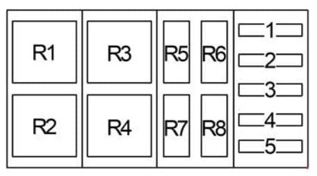
Additional Relay Box No.2
| Number | Ampere rating [A] | Description |
| 1 | 30 | Trailer tow ABS feed (non electric trailer brake vehicles only) |
| 2 | 30 | Trailer tow park/marker lamps |
| 3 | 30 | Trailer tow stop lamps |
| 4 | 30 | Trailer tow turn/stop lamps (combined) Trailer tow turn lamps (separate) |
| 5 | — | — |
| Relay | ||
| R1 | Trailer tow ABS relay (non electric trailer brake vehicles only) | |
| R2 | Trailer tow marker lamp relay | |
| R3 | Trailer tow stop lamp relay | |
| R4 | Trailer tow tail lamp relay | |
| R5 | — | |
| R6 | — | |
| R7 | Trailer tow left turn lamp relay | |
| R8 | Trailer tow right turn lamp relay | |
WARNING: Terminal and harness assignments for individual connectors will vary depending on vehicle equipment level, model, and market.


