Year of production: 2009, 2010, 2011, 2012, 2013
Importing this car? Don't forget to calcular iva 23%.
Passenger compartment fuse box
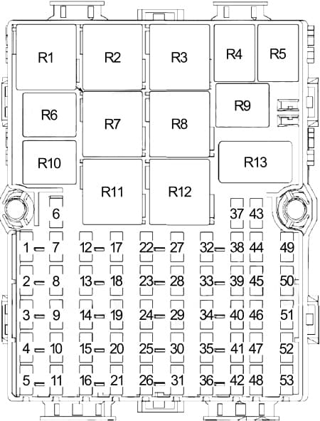
| No. | A | Circuits |
| 1 | 15 | Generic Electronic Module (GEM) |
| 2 | 5 | Exterior Rear View Mirror Switch |
| 3 | 10 | Main Light Switch, Generic Electronic Module (GEM) |
| 4 | — | — |
| 5 | — | — |
| 6 | — | — |
| 7 | 15 | Generic Electronic Module (GEM) |
| 8 | 7,5 | Audio Control Module (ACM), Instrument Cluster (IC), Tire Pressure Monitoring System (TPMS) Module |
| 9 | — | — |
| 10 | — | — |
| 11 | — | — |
| 12 | 10 | Main Light Switch |
| 13 | 15 | Brake Pedal Position Switch |
| 14 | 15 | Cigar Lighter (Front) |
| 15 | — | — |
| 16 | — | — |
| 17 | 20 | Front Wiper Relay, Generic Electronic Module (GEM), Windshield Wiper Motor |
| 18 | — | — |
| 19 | 7,5 | Generic Electronic Module (GEM), Instrument Cluster (IC) |
| 20 | — | — |
| 21 | — | — |
| 22 | 15 | Audio Control Module (ACM), Speech Recognition Module (SRM) |
| 23 | 7,5 | A/C Switch, Parking Aid Module (PAM) |
| 24 | 7,5 | Interior Lamps Relay |
| 25 | — | — |
| 26 | — | — |
| 27 | 7,5 | Right Marker, Side and Park Lamps |
| 28 | 7,5 | License Plate Lamps |
| 29 | 10 | Main Light Switch |
| 30 | — | — |
| 31 | — | — |
| 32 | 7,5 | Anti-lock Brake System (ABS) Module, Steering Angle Sensor Module |
| 33 | 7,5 | Occupant Classification System Module (OCSM), Passenger Air Bag Deactivation (PAD) indicator, Restraints Control Module (RCM) |
| 34 | 20 | Generic Electronic Module (GEM), Rear Door Unlock Relay |
| 35 | — | — |
| 36 | — | — |
| 37 | 25 | Master Window Control Switch, One-Touch Down Window Relay |
| 38 | 7,5 | Exterior Rearview Mirrors, Defrost Switch |
| 39 | — | — |
| 40 | 15 | Power Point |
| 41 | — | — |
| 42 | — | — |
| 43 | — | — |
| 44 | — | — |
| 45 | 15 | Rear Power Point |
| 46 | 7,5 | Left Marker, Side and Park Lamps |
| 47 | — | — |
| 48 | — | — |
| 49 | 25 | Rear Window Defrost Grids |
| 50 | 7,5 | Generic Electronic Module (GEM), Instrument Cluster (IC), Passive Anti-Theft Transceiver, Tire Pressure Monitoring System (TPMS) Module |
| 51 | 20 | Generic Electronic Module (GEM), Wiper/Washer Switch, Rear Wiper Motor Assembles |
| 52 | — | — |
| 53 | — | — |
| Relay | ||
| R1 | — | — |
| R2 | — | — |
| R3 | — | — |
| R4 | — | Interior Light |
| R5 | — | Front Wiper |
| R6 | — | Low Beam Interput |
| R7 | — | Rear Window Defogger |
| R8 | — | — |
| R9 | — | Rear Door Unlock |
| R10 | — | — |
| R11 | — | Blower Motor |
| R12 | — | — |
| R13 | — | — |
Engine compartment fuse box
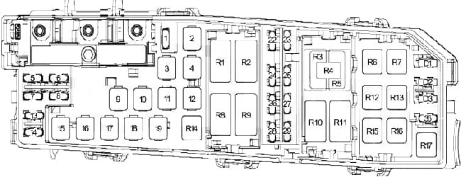
| No. | A | Circuits |
| 1 | — | — |
| 2 | 40 | Fuses (Passenger Compartment) no: 12, 13, 17, 37, 51 |
| 3 | 20 | Ignition Switch |
| 4 | 20 | Fuel Pump Relay |
| 5 | 10 | Keep Alive Power (PCM), Evaporative Emission (EVAP) Canister Vent Control Solenoid |
| 6 | 15 | Generator, Data Link Connector (DLC) |
| 7 | 10 | Reverse Lamp Relay |
| 8 | 15 | High Beam Relay |
| 9 | 40 | Fuses (Passenger Compartment): no. 1 ,2 ,3, 14 |
| 10 | 30 | Fuses (Passenger Compartment): no. 7, 19, 22, 25, 34, 40 ,45 |
| 11 | 30 | Starter relay |
| 12 | 30 | Anti-Lock Brake System (ABS) Module |
| 13 | 30 | Blower Motor Relay |
| 14 | 10 | Powertrain Control Module (PCM) Power Relay |
| 15 | 20 | Anti-Lock Brake System (ABS) Module |
| 16 | 30 | Low Speed Fan Control Relay |
| 17 | 50 | High Speed Fan Control Relay |
| 18 | 20 | Daytime Running Lamps Relay, Low Beam Interrupt Relay |
| 19 | 20 | Tire Pressure Monitoring System (TPMS) Module |
| 22 | 10 | Fuel Injectors, Powertrain Control Module (PCM) |
| 23 | 10 | Right Low Beam |
| 24 | 10 | A/C Clutch Relay |
| 25 | 10 | Left Low Beam |
| 26 | 10 | Evaporative Emission (EVAP) Canister Purage Valve, Heated Oxygen Sensor (HO2S), Reverse Lamp Relay, Exhaust Gas Recirculation (EGR), Stepper Motor, Mass Air Flow/intake Air Temperature (MAF/IAT) Sensor, Transmission Range (TR) Sensor, Pedal Position Switch, Floor Shiffer |
| 27 | — | — |
| 28 | 15 | Powertrain Control Module (PCM) |
| 29 | 15 | (Coil on Plug) |
| 35 | 10 | Powertrain Control Module (PCM) |
| Relay | ||
| R1 | — | Ignition |
| R2 | — | — |
| R3 | — | — |
| R4 | — | High Speed Fan Control |
| R5 | — | — |
| R6 | — | Reverse Light |
| R7 | — | Fuel Pump |
| R8 | — | High Beam |
| R9 | — | Powertrain Control Module (PCM) Power |
| R10 | — | Low S[eed Fan Control |
| R11 | — | Starter |
| R12 | — | Daytime Running Light (DRL) |
| R13 | — | Low Beam |
| R14 | — | A/C Clutch |
| R15 | — | — |
| R16 | — | — |
| R17 | — | — |
| Diode | ||
| D1 | — | Cooling Fan |
| D2 | — | Fuel Pump |
| D3 | — | Start |
WARNING: Terminal and harness assignments for individual connectors will vary depending on vehicle equipment level, model, and market.