Year of production: 2014, 2015, 2016, 2017, 2018
Importing this car? Don't forget to calcular iva 23%.
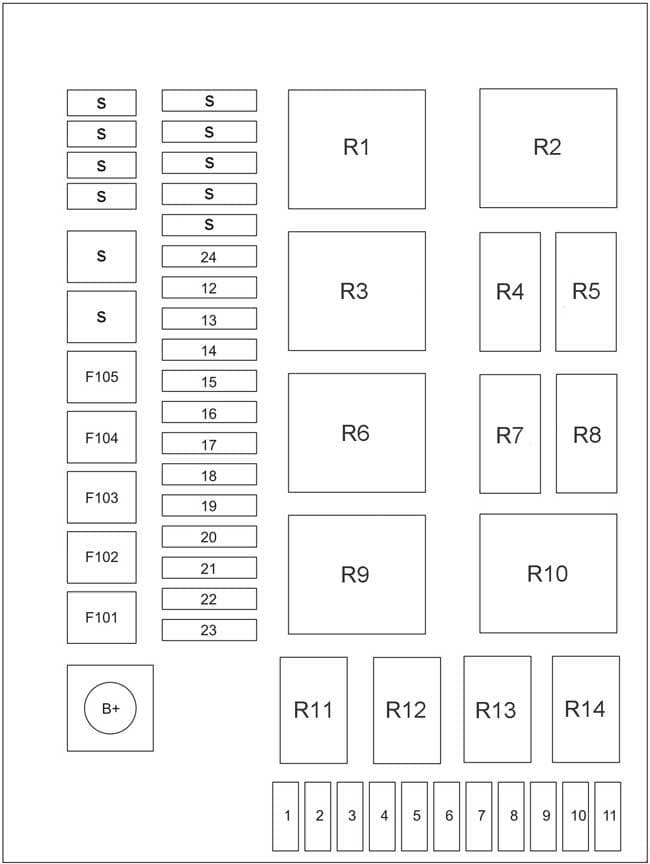
Passenger Compartment Fuse Panel
| Number | A | Component |
| 1 | 10 | A/C |
| 2 | 10 | Rear wiper |
| 3 | 25 | Defrosting |
| 4 | 20 | Front wiper |
| 5 | 10 | Back-up lamps |
| 6 | 20 | Window Lift |
| 7 | 10 | ACC |
| 8 | 25 | Cigar Lighter, standby power supply |
| 9 | 10 | Combination instrument |
| 10 | 15 | Engine Control Module |
| 11 | 15 | Air bag |
| 12 | 30 | Electric seat |
| 13 | 10 | Interior Lighting |
| 14 | 15 | PEPS |
| 15 | 20 | MP5/CD |
| 16 | 20 | Body Control Module (BCM) |
| 17 | 20 | Body Control Module (BCM) |
| 18 | 20 | Body Control Module (BCM) |
| 19 | 20 | Body Control Module (BCM) |
| 20 | 20 | Body Control Module (BCM) |
| 21 | 20 | Body Control Module (BCM) |
| 22 | 20 | Body Control Module (BCM) |
| 23 | 10 | Always energized |
| 24 | 25 | Moon roof |
| 101 | 40 | Blower Motor |
| 102 | 30 | Window Lift |
| 103 | 30 | IG2 Relay |
| 104 | 40 | IG1 Relay and ACC |
| 105 | 40 | Defrosting relay |
| S | — | Spare |
| R1 | — | |
| R2 | Blower Motor | |
| R3 | — | |
| R4 | ACC | |
| R5 | IG1 | |
| R6 | — | |
| R7 | Defrosting | |
| R8 | Window Lift | |
| R9 | — | |
| R10 | Air blower high speed relay | |
| R11 | Front wiper | |
| R12 | Front wiper high speed relay | |
| R13 | Rear wiper | |
| R14 | IG2 | |
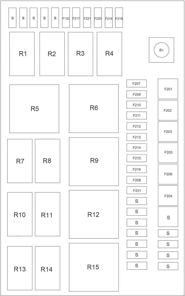
Fuse Box In The Engine Compartment
| Number | A | Component |
| 132 | 20 | Transmission Control Module |
| 201 | 30 | Cooling fan low speed |
| 202 | 40 | Cooling fan high speed |
| 203 | 40 | ABS |
| 204 | 40 | ESP |
| 205 | 40 | High Beam relay, Low Beam relay |
| 206 | 40 | Starter relay |
| 207 | 10 | Engine Control Module |
| 208 | 20 | Headlamp Washer |
| 209 | 20 | A/C compressor |
| 210 | 10 | 4WD |
| 211 | 10 | Horn |
| 212 | 15 | Fuel pump |
| 213 | 25 | ABS |
| 214 | 10 | Stop Lamp |
| 215 | 20 | Electric vacuum pump |
| 216 | 20 | Main relay |
| 217 | 15 | Ignition |
| 218 | 10 | Low beam headlamps (right) |
| 219 | 10 | Low beam headlamps (left) |
| 2210 | 15 | High Beam |
| 221 | 10 | Heated Oxygen Sensor |
| 232 | 20 | Transmission Control Module |
| S | — | Spare |
| Relay | ||
| R1 | Electric vacuum pump | |
| R2 | Low Beam | |
| R3 | High Beam | |
| R4 | Horn | |
| R5 | Main relay | |
| R6 | Driver circuit relay | |
| R7 | Fuel pump | |
| R8 | A/C compressor | |
| R9 | Cooling fan high speed | |
| R10 | Solenoid shift valve | |
| R11 | Headlamp Washer | |
| R12 | Starter | |
| R13 | — | |
| R14 | — | |
| R15 | Cooling fan low speed | |
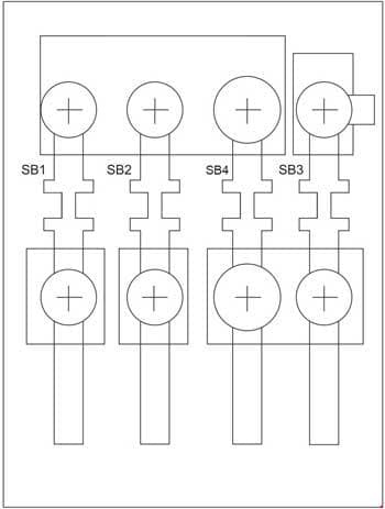
Fuse Block on Positive Battery Terminal
| Number | A | Component |
| SB1 | 80 | Passenger Compartment Fuse Panel |
| SB2 | 100 | Engine Compartment Fuse Box |
| SB3 | 80 | Alternator |
| SB4 | 150 | Fuses SB1, SB2, SB3 |
WARNING: Terminal and harness assignments for individual connectors will vary depending on vehicle equipment level, model, and market.


