Year of production: 2010, 2011, 2012, 2014
Importing this car? Don't forget to calcular iva 23%.
Passenger Compartment
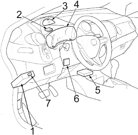
- Fuse Box
- Tire Pressure Monitoring System (TPMS) Control Unit
- Gauge Control Module
- Gauge Control Module
- Supplemental Restraint System (SRS) Unit
- Electronic Power Steering (EPS) Control Unit
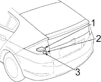
- Hatch Release Actuator Relay
Passenger Compartment Fuse Box

| No. |
A |
Protected Component |
| 1 | 15 | Audio-Navigation Unit (With Navigation), Audio Unit (Without Navigation), Cargo Area Light, Ceiling Light, Data Link Connector (DLC), Gauge Control Module, Immobilizer-Keyless Control Unit, HandsFreeLink Control Unit, Individual Map Light, Multiplex Integrated Control Unit (MICU) (+B BACK UP), Motor Control Module (MCM) |
| 2 | 7.5 | Tire Pressure Monitoring System (TPMS) Control Unit |
| 3 | 20 | Power Window Master Switch |
| 4 | – | – |
| 5 | 10 | Back-up Light, Multiplex Integrated Control Unit (MICU) |
| 6 | 10 | Supplemental Restraint System (SRS) Unit |
| 7 | 10 | Powertrain Control Module – PCM (VBSOL) |
| 8 | 7.5 | Occupant Detection System (ODS) Unit, Front Passenger’s Airbag Cutoff Indicator, Supplemental Restraint System (SRS) Unit |
| 9 | – | – |
| 10 | 7.5 | A/C Compressor Clutch Relay, Blower Motor Relay, Climate Control Unit, Fan Control Relay (A/C Diode A), Optional Connector, Power Mirror Switch, Radiator Fan Relay (A/C Diode A), Rear Window Defogger Relay, Recirculation Control Motor |
| 11 | 7.5 | EPS Control Unit (IG1), VSA Modulator-control Unit (IG1), Yaw Rateacceleration Sensor (With VSA), ABS Modulator-Control Unit (MTR) (Without VSA) |
| 12 | 10 | DC-DC Converter, Evaporative Emission Control (EVAP) Canister Purge Valve, Powertrain Control Module – (Idle Stop Switch), Mass Air Flow (MAF) Sensor, Secondary Heated Oxygen Sensor (HO2S) |
| 13 | 20 | Accessory Power Socket |
| 14 | 7.5 | Audio-Navigation Unit (With Navigation), Audio Unit (Without Navigation), Key Interlock Solenoid, HandsFreeLink Control Unit, MICU (ACC), Optional Connector |
| 15 | 7.5 | Daytime Running Light, Multiplex Integrated Control Unit (MICU) |
| 16 | 10 | Rear Window Wiper Motor |
| 17 | 20 | Front Passenger’s Power Window Motor, Front Passenger’s Power Window Switch Light |
| 18 | 20 | Right Rear Power Window Motor, Power Window Master Switch, Right Rear Power Window Switch Light |
| 19 | 20 | Left Rear Power Window Motor, Power Window Master Switch, Left Rear Power Window Switch Light |
| 20 | 15 | Fuel Pump (PGM-FI Main Relay No.2 (’12-’14)), Immobilizer-Keyless Control Unit, Powertrain Control Module – PCM (IG1) (’12-’14) |
| 21 | 15 | Washer Motor, Multiplex Integrated Control Unit (MICU) |
| 22 | 7.5 | Electrical Load Detector (ELD), Gauge Control Module, Multiplex Integrated Control Unit – MICU (IG1 METER), Motor Control Module (MCM), Shift Lock Solenoid, Tire Pressure Monitoring System (TPMS) Control Unit |
| 23 | 10 | Turn Signal/Hazard Relay, Multiplex Integrated Control Unit (MICU) |
| 24 | 10 | Brake Pedal Position Switch, High Mount Brake Light, Left Brake Light, Right Brake Light, Horn Relay, Multiplex Integrated Control Unit (MICU), Powertrain Control Module (PCM) |
| 25 | – | – |
| 26 | 10 | Air Fuel Ratio (A/F) Sensor, Evaporative Emission Control (EVAP) Canister Vent Shut Valve, Fuse: No. 31 (7.5 A) |
| 27 | 30 | Power Door Lock, Multiplex Integrated Control Unit (MICU) |
| 28 | 20 | Headlamp (Main), Multiplex Integrated Control Unit (MICU) |
| 29 | 10 | Parking Light, Multiplex Integrated Control Unit (MICU) |
| 30 | 30 | Radiator Fan Motor (Radiator Fan Relay), A/C Condenser Fan Motor (Fan Control Relay) (’12-’14) |
| 31 | 7.5 | A/C Condenser Fan Relay (A/C Diode B) |
| 32 | 10 | Right Headlight (Low Beam) |
| 33 | 20 | Ignition Coil Relay, Fuses (Engine Compartment): No.1 (15 A), 2 (15 A) |
| 34 | 10 | Left Headlight (Low Beam) |
| 35 | 15 | Front Passenger’s Door Lock Actuator, Right Rear Door Lock Actuator |
| 36 | 15 | Driver’s Door Lock Actuator, Left Rear Door Lock Actuator |
| 37 | 30 | ABS Modulator-Control Unit (Without VSA), VSA Modulator-Control Unit |
| 38 | 15 | Driver’s Door Lock Actuator |
| 39 | 15 | Crankshaft Position (CKP) Sensor, Camshaft Position (CMP) Sensor, Electronic Throttle Control System (ETCS) Control Relay, Injectors, Powertrain Control Module – PCM (IGP), PGM-FI Main Relay No.1, PGM-FI Main Relay No.2 (Fuel Pump) |
| 40 | – | – |
| 41 | – | – |
| 42 | 10 | Motor Control Module (MCM), MCM Relay No.1, MCM Relay No.2 |
| 43 | 7.5 | A/C Compressor (A/C Compressor Clutch Relay) |
| 44 | 7.5 | Starter Cut Relay, Powertrain Control Module – PCM (STS) |
| 45 | 7.5 | Hatch Release Actuator Relay, Hatch Release Actuator |
| 46 | – | – |
| 47 | 30 | A/C Condenser Fan Motor (A/C Condenser Fan Relay), Radiator Fan Motor (Fan Control Relay) (’10-’11) |
| 48 | 10 | Left Headlight (High Beam) |
| 49 | 15 | Front Passenger’s Door Lock Actuator, Right Rear Door Lock Actuator |
| 50 | 15 | Left Rear Door Lock Actuator |
| 51 | 10 | Right Headlight (High Beam) |
| 52 | 15 | Electronic Throttle Control System (ETCS) Control Relay, Powertrain Control Module – PCM (IG1ETCS) |
| 53 | 10 | Intelligent Power Unit (IPU) Module Fan (Motor Control Module (MCM) Relay No.2), Motor Power Inverter (MPI) Module (Motor Control Module (MCM) Relay No.2) |
| 54 | – | – |
| 55 | 10 | Left Power Mirror Defogger, Right Power Mirror Defogger |
| 56 | 30 | Front Wiper, Multiplex Integrated Control Unit (MICU) |
| 57 | 30 | Blower Motor (Blower Motor Relay) |
| 58 | 30 | ABS Modulator-Control Unit (Without VSA), VSA Modulator-Control Unit |
| 59 | 30 | Without Power Mirror Defogger: Rear Window Defogger Relay (Lower Rear Window Defogger, Upper Rear Window Defogger, Noise Reduction Condenser) |
| 40 | With Power Mirror Defogger: Rear Window Defogger Relay (Lower Rear Window Defogger, Upper Rear Window Defogger, Noise Reduction Condenser, Fuse: No.55 (10 A)) | |
| 60 | 50 | Ignition switch |
| 30 | Headlamp Washer | |
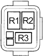
| Relay | ||
| R1 | Power Window | |
| R2 | Blower Motor | |
| R3 | Air Fuel Ratio (A/F) Sensor | |
| R4 | Lighting | |
| R5 | Ignition Coil | |
| R6 | PGM-FI Main No.1 | |
| R7 | Electronic Throttle Control System (ETCS) Control | |
| R8 | Rear Window Defogger | |
| R9 | Driver’s Door Unlock | |
| R10 | Starter Cut | |
| R11 | – | |

- Immobilizer-Keyless Control Unit
- Climate Control Unit
- Audio-Navigation Unit (With Navigation), Audio Unit (Without Navigation)
- HandsFreeLink Control Unit
- Motor Control Module (MCM)
- Motor Control Module (MCM) Relay No.1
- Motor Control Module (MCM) Relay No.2
Engine Compartment
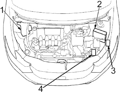
- ABS Modulator-Control Unit (Without VSA), VSA Modulator-Control Unit
- Powertrain Control Module (PCM)
- Relay Box No.1
- Relay Box No.2
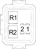
Engine Compartment Relay Box No.1
| No. |
A |
Protected Component |
| 1 | 15 | Exhaust Side Ignition Coils |
| 2 | 15 | Intake Side Ignition Coils |
| Relay | ||
| R1 | Fan Control | |
| R2 | PGM-FI Main No.2 (Fuel Pump) | |
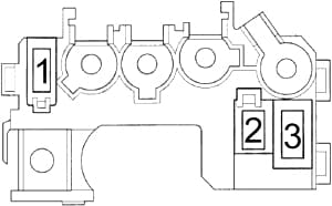
Engine Compartment Relay Box No.2
| No. |
Protected Component |
| R1 | A/C Condenser Fan |
| R2 | Radiator Fan |
| R3 | A/C Compressor Clutch |
Battery Terminal Fuse Box
These fuses are not serviceable; replace the battery terminal fuse box as an assembly.
| No. |
A |
Protected Component |
| 1 | 100 | DC-DC Converter, Lighting Relay, Power Window Relay, Driver’s Door Unlock Relay, Fuses: No. 1, 2, 3, 9, 17, 18, 19, 25, 26, 27, 28, 29, 30, 32, 33, 34, 37, 38, 39, 40, 41, 42, 43, 45, 46, 47, 52, 53, 57, 58, 59, 60 |
| 2 | 60 | Electronic Power Steering (EPS) Control Unit |
| 3 | 20 | Fuses: 23, 24 |
WARNING: Terminal and harness assignments for individual connectors will vary depending on vehicle equipment level, model, and market.