Year of production: 2008, 2009, 2009, 2010, 2011, 2012, 2013, 2014, 2015, 2016, 2017
Importing this car? Don't forget to calcular iva 23%.
The Instrument Panel Fuse Panel (J/B)
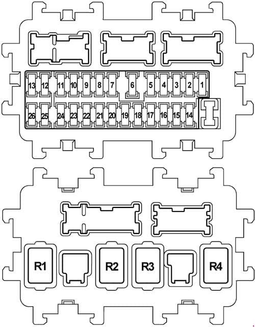
| Number | A | Description |
| 1 | — | — |
| 2 | 10 | Occupant Detection System Control Unit Air Bag Diagnosis Sensor Unit |
| 3 | 10 | Front Combination Lamp RH Front Combination Lamp LH Ionizer Climate Controlled Seat Relay Unified Meter And A/C Amp. Low Tire Pressure Warning Control Unit Can Gateway AV Control Unit Exhaust Gas / Outside Odor Detecting Sensor Auto Anti-dazzling Inside Mirror ICC Brake Hold Relay ASCD Brake Switch Stop Lamp Switch AFS Control Unit Data Link Connector Warning Systems Switch Lane Departure Warning Buzzer Lane Camera Unit Compressor Tel Adapter Unit Heated Seat Relay Heated Seat Switch (Driver Side) Heated Seat Switch (Passenger Side) |
| 4 | 10 | Combination Meter Back-up Lamp Relay Around View Monitor Control Unit Sonar Control Unit |
| 5 | 20 | Accessory Relay |
| 6 | 10 | Key /slot Clock Data Link Connector Rain Sensor Intelligent Key Warning Buzzer Auto Anti-Dazzling Inside Mirror |
| 7 | 10 | ICC Brake Hold Relay Stop Lamp Switch Body Control Module (BCM) |
| 8 | 20 | Bose (audio system) |
| 9 | 10 | Key Slot Push-Button Ignition Switch |
| 10 | 10 | Body Control Module (BCM) Automatic Drive Positioner Control Unit Total Illumination Control Unit Seat Memory Switch Drive Seat Control Unit |
| 11 | 10 | Combination Meter Unified Meter and A/C Amp. AWD Control Unit CAN Gateway Pre-Crash Seat Belt Control Unit (Driver Side / Passenger Side) |
| 12 | — | Spare |
| 13 | — | Spare |
| 14 | — | — |
| 15 | 10 | Door Mirrors |
| 16 | 20 | Rear Windows Defogger |
| 17 | 20 | Rear Windows Defogger |
| 18 | 10 | E-SUS Control Unit |
| 19 | — | — |
| 20 | 15 | Front Power Socket |
| 21 | 10 | Door Mirror Remote Control Switch Unified Meter And A/C Amp. Multifunction Switch Total Illumination Control Unit AV Control Unit Around View Monitor Control Unit Tel Adapter Unit Satellite Radio Tuner |
| 22 | 20 | Console Power Socket Rear Power Socket |
| 23 | 15 | Blower Motor |
| 24 | 15 | Blower Motor |
| 25 | — | Spare |
| 26 | — | Spare |
| Relay | ||
| R1 | Ignition Relay | |
| R2 | Rear Windows Defogger Relay | |
| R3 | Accessory Relay | |
| R4 | Blower Relay | |
Fuse Box In The Engine Compartment (IPDM E/R)
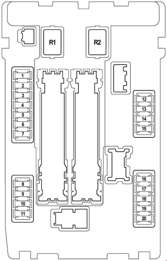
| Number | A | Description |
| 1 | 15 | Fuel Pump Relay Fuel Pump Control Module Fuel Level Sensor Unit Fuel Pump Engine Control Module (ECM) |
| 2 | 10 | Cooling Fan Relay 2 |
| 3 | 10 | Transmission Control Module (TCM) Snow Mode Switch |
| 4 | 10 | Fuel Injector No. 1 Fuel Injector No. 2 Fuel Injector No. 3 Fuel Injector No. 4 Fuel Injector No. 5 Fuel Injector No. 6 Fuel Injector No. 7 (VK engine) Fuel Injector No. 8 (VK engine) Engine Control Module (ECM) Body Control Module (BCM) Total Illumination Control Unit |
| 5 | 10 | ICC Sensor Integrated Unit Accelerator Pedal Actuator ABS Actuator And Electric Unit (Control Unit) Steering Angle Sensor Yaw Rate 1 Side G Sensor AWD Control Unit Power Steering Control Unit RAS Control Unit ICC Warning Chime Brake Booster Control Unit |
| 6 | 15 | Heated Oxygen Sensor 2 (Bank 2) Heated Oxygen Sensor 2 (Bank 1) Air Fuel Ratio (A/F) Sensor 1 (Bank 1) Air Fuel Ratio (A/F) Sensor 1 (Bank 2) |
| 7 | 10 | Combination Switch |
| 8 | — | — |
| 9 | 10 | A/C Relay Compressor |
| 10 | 15 | ECM Relay Engine Control Module (ECM) Condensor Intake Valve Timing Control Solenoid Valve Intake Valve Timing Control Solenoid Valve (Bank 1) Intake Valve Timing Control Solenoid Valve (Bank 2) Exhaust Valve Timing Control Solenoid Valve (Bank 1) Exhaust Valve Timing Control Solenoid Valve (Bank 2) EVAP Canister Vent Control Valve Ignition Coil No.1 (with Power Transistor) Ignition Coil No.2 (with Power Transistor) Ignition Coil No.3 (with Power Transistor) Ignition Coil No.4 (with Power Transistor) Ignition Coil No.5 (with Power Transistor) Ignition Coil No.6 (with Power Transistor) Ignition Coil No.7 (with Power Transistor; VK engine) Ignition Coil No.8 (with Power Transistor; VK engine) EVAP Canister Purge Volume Control Solenoid Valve Mass Air Flow Sensor (Bank 2) Mass Air Flow Sensor (Bank 1) VVEL Control Module |
| 11 | 15 | Throttle Control Motor Relay Engine Control Module (ECM) |
| 12 | 10 | Front Combination Lamp LH (Tail Lamp) Front Combination Lamp RH (Tail Lamp) |
| 13 | 10 | Rear Combination Lamp LH Rear Combination Lamp RH License Plate Lamp LH License Plate Lamp RH Glove Box Lamp Total Illumination Control Unit Front Power Socket ATT Shift Selector AV Control Unit |
| 14 | 10 | Front Combination Lamp LH (High Beam) |
| 15 | 10 | Front Combination Lamp RH (High Beam) |
| 16 | 15 | Headlamp LH (Low Beam) |
| 17 | 15 | Headlamp RH (Low Beam) |
| 18 | 10 | Front Fog Lamp Relay (Front Fog Lamp LH, Front Fog Lamp RH) |
| 19 | — | — |
| 20 | 30 | Front Wiper Relay |
| Relay | ||
| R1 | — | |
| R2 | Starter Control Relay | |
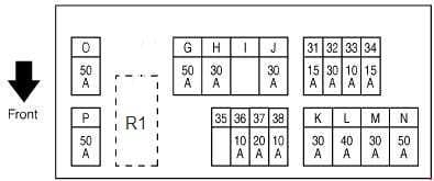
Fuse Box In The Engine Compartment (E12)

| Number | A | Description |
| 31 | 15 | Horn Relay 1 Alternator |
| 32 | 30 | Option Connector |
| 33 | 10 | AWD Control Unit Brake Booster Control Unit |
| 34 | 15 | Front Display Unit AV Control Unit Around View Monitor Control Unit Woofer Satellite Radio Tuner Tel Adapter Unit |
| 35 | — | — |
| 36 | 10 | Transmission Control Module (TCM) |
| 37 | 20 | RAS Motor Relay |
| 38 | 10 | Horn Relay 2 |
| G | 50 | VVEL Actuator Motor Relay |
| H | 30 | Fuse Block J/B IPDM E/R |
| I | — | — |
| J | 30 | Pre-Crash Seat Belt Control Unit (Driver Side) |
| K | 30 | Pre-Crash Seat Belt Control Unit (Passenger Side) |
| L | 40 | Body Control Module (BCM) Automatic Drive Positioner Cont Driver Seat Control Unit Lumbar Support Switch Side Support Unit Power Seat Switch |
| M | 30 | ABS Actuator and Electronic Unit |
| N | 50 | ABS Actuator and Electronic Unit |
| O | 50 | Cooling Fan Relay 1 |
| P | 50 | Fuse Block E213 – Fuse No.: Q (Automatic Back Door Control Unit), 61 (Accelerator Pedal Actuator), 62 (Climate Controlled Seat Relay), 63 (Climate Controlled Seat Relay, Heated Seat Relay) |
| Relay | ||
| R1 | Horn Relay 1 | |
Fuse Block on Positive Battery Terminal
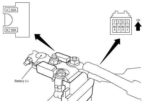
| Number | A | Description |
| A | 250 | Starter Motor Alternator Fuse No.: C. D, E |
| B | 100 | Fuse No.: O (Cooling Fan Relay 1), S (Cooling Fan Relay 2) |
| C | 100 | Fuse and Fusible Link Block |
| D | 80 | Fuse Block J/B (Fuse No.: 5, 6, 7, 8, 9, 10, 11) To Accessory Power Supply To Ignition Power Supply |
| E | 100 | IPDM E/R (Fuse No.: 10, 11) To Ignition Power Supply |
| F | 60 | IPDM E/R (Fuse No.: 18 (Front Fog Lamp Relay); Headlamp High Relay, Headlamp Low Relay, Tail Lamp Relay) To Ignition Power Supply |
Fuse Box In The Engine Compartment (E212; VK engine)
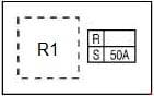
| Number | A | Description |
| R | — | — |
| S | 50 | Cooling Fan Relay 2 |
| Relay | ||
| R1 | Cooling Fan Relay 2 | |
Fuse Box In The Engine Compartment (E213)
| Number | A | Description |
| 61 | 15 | Accelerator Pedal Actuator |
| 62 | 15 | Climate Controlled Seat Relay |
| 63 | 10 | Climate Controlled Seat Relay Heated Seat Relay |
| Q | 30 | Automatic Back Door Control Unit |
| Relay | ||
| R6 | Horn Relay 2 | |
| R8 | ICC Brake Hold Relay | |
WARNING: Terminal and harness assignments for individual connectors will vary depending on vehicle equipment level, model, and market.