In this article you will find a description of fuses and relays Isuzu,
with photos of block diagrams and their locations.
Highlighted the cigarette lighter fuse (as the most popular thing people look for).
Get tips on blown fuses, replacing a fuse, and more.
Year of production: 2008
Engine compartment
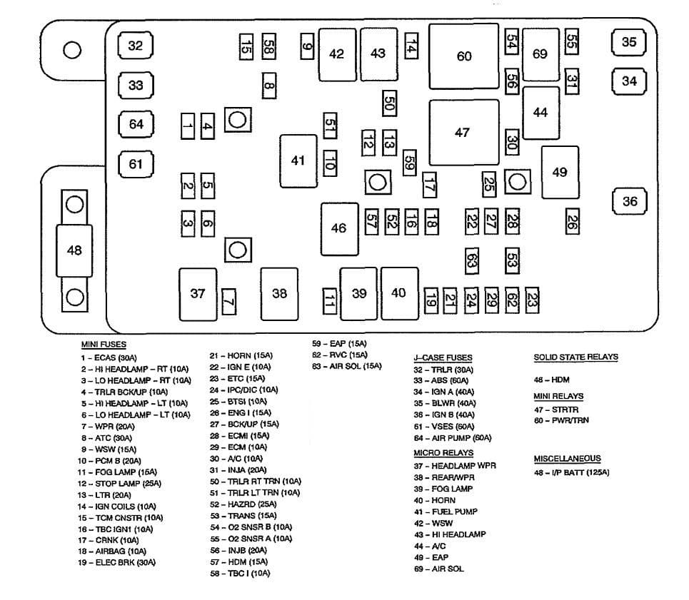
| No | Fuse name | A | Description |
| 1 | ECAS Fuse | 30 | Air Suspension Compressor Assembly |
| 2 | HI HEADLAMP-RT Fuse | 10 | Headlamp – High Beam – Right |
| 3 | LO HEADLAMP-RT Fuse | 10 | Head lamp – Low Beam – Right |
| 4 | TRLR BCK/UP Fuse | 10 | Trailer Connector |
| 5 | HI HEADLAMP-LT Fuse | 10 | Headlamp- High Beam – Left |
| 6 | LO HEADLAMP-LT Fuse | 10 | Headlamp – Low Beam – Left |
| 7 | WPR Fuse | 20 | HEADLAMP WPR Relay, REAR/WPR Relay |
| 8 | ATC Fuse | 30 | Transfer Case Encoder .Motor, Transfer Case Shift Control Module |
| 9 | WSW Fuse | 15 | WSW Relay |
| 10 | PCM B Fuse | 20 | FUEL PUMP Relay |
| 11 | FOG LAMP Fuse | 15 | FOG LAMP Relay |
| 12 | STOP LAMP Fuse | 25 | Stop Lamp Switch |
| 13 | LTR Fuse | 20 | Cigar Lighter, Data Link Connector (DLC) |
| 14 | IGN COILS Fuse | 10 | HI HEADLAMP Relay |
| 15 | TCM CNSTR Fuse | 10 | Evaporative Emission (EVAP) Canister Vent Solenoid, Transmission Control Module (TCM) |
| 16 | TBC IGN1 Fuse | 10 | Body Control Module (BCM) |
| 17 | CRNK Fuse | 10 | Engine Control Module (PCM) |
| 18 | AIR BAG Fuse | 10 | Inflatable Restraint Front Passenger Pressure System (PPS) Module, Inflatable Restraint Sensing and Diagnostic Module (SDM), Rollover Sensor |
| 19 | ELEC BRK Fuse | 30 | Trailer Brake Wiring |
| 21 | HORN Fuse | 15 | HORN Relay |
| 22 | IGN E Fuse | 10 | A/C Relay, Headlamp l eveling Actuators, Headlamp Switch, Inside Rearview Mirror, Instrument Panel Cluster (I PC), Park/Neutral Position (PNP) Switch, Stop Lamp Switch, Turn Signal/Multifunction Switch |
| 23 | ETC Fuse | 15 | IIEngine Control Module (ECM) |
| 24 | IPC/DIC Fuse | 10 | Instrument Panel Cluster (IPC) |
| 25 | BTSI Fuse | 10 | Automatic Transmission Shift Lock Actuator, Stop Lamp Switch |
| 26 | ENG I Fuse | 15 | Evaporative Emission (EVAP) Canister Purge Solenoid, Mass Air Flow (MAF)/Intake Air Temperature (IAT) Sensor, Valve Lifter Oil Manifold (VLOM) Assembly |
| 27 | BCK/UP Fuse | 15 | EAP Relay, Park/Neutral Position (PNP) Switch |
| 28 | ECMI Fuse | 15 | Engine Control Module (ECM) |
| 29 | ECM Fuse | 10 | Engine Control Module (ECM) |
| 30 | A/C Fuse | 10 | A/C Relay |
| 31 | INJA Fuse | 10 | odd Fuel Injectors, Odd Ignition Coils |
| 32 | TRLR Fuse | 30 | Trailer Connector |
| 33 | ABS Fuse | 60 | Electronic Brake Control Module (EBCM) |
| 34 | IGN A Fuse | 40 | Ignition Switch- ACCY/RUN/START, RUN, START BUS |
| 35 | BLWR Fuse | 40 | Blower Motor Control Module, Blower Motor Resistor Assembly |
| 36 | IGN B Fuse | 40 | Ignition Switch – ACCY/RUN, RUN/START BUS |
| 37 | HEADLAMP WPR Relay | — | Headlamp Washer Fluid Pump |
| 38 | REAR/WPR Relay | — | Rear Window Washer Fluid Pump |
| 39 | FOG LAMP Relay | — | Front Fog Lamps |
| 40 | HORN Relay | — | Horn Assembly |
| 41 | FUEL PUMP Relay | — | Fuel Pump and Sender Assembly |
| 42 | WSW Relay | — | Windshield Washer Fluid Pump |
| 43 | HI HEADLAMP Relay | — | HI HEADLAMP- LT Fuse, HI HEADLAMP-RT Fuse |
| 44 | A/C Relay | — | A/C Compressor Clutch Assembly |
| 45 | FAN Relay | — | Cooling Fan |
| 46 | HDM Relay | — | LO HEADLAMP- L T Fuse, LO HEADLAMP-RT Fuse |
| 47 | STRTR Relay | — | Starter |
| 48 | I/P BATT Fuse | 125 | Fuse Block- Rear – B+ Bus |
| 49 | EAP Relay | — | Electronic Adjustable Pedals (EAP) Switch |
| 50 | TRLR RT TRN Fuse | 10 | Trailer Connector |
| 51 | TRLR LT TRN Fuse |
10 | Trailer Connector |
| 52 | HAZRD Fuse | 25 | Turn Signal/Hazard Flasher Module |
| 53 | TRANS Fuse | 15 | Automatic Transmission, Transmission Control Module (TCM) |
| 54 | O2 SNSR B Fuse | 10 | Heated Oxygen Sensor (H02S) Bank 1/2 Sensor 2 |
| 55 | O2 SNSR B Fuse | 10 | Heated Oxygen Sensor (H02S) Bank 1/2 Sensor 1 |
| 56 | INJB Fuse | 20 | IIEven Fuel Injectors, Even Ignition Coils |
| 57 | HDM Fuse | 15 | HDM Relay |
| 58 | TBC I Fuse | 10 | Body Control Module (SCM), Theft Deterrent Alarm, Theft Deterrent Control Module |
| 59 | EAP Fuse | 15 | EAP Relay, Electronic Adjustable Pedals (EAP) Relay |
| 60 | PWR/TRN RELAY | — | ENGI Fuse, ETC Fuse, INJA Fuse, INJB Fuse, 02 SNSR A Fuse, 02 SNSR B Fuse |
| 61 | VSES Fuse | 60 | Eiectronic Brake Control Module (EBCM) |
| 62 | RVC Fuse | 15 | Regulated Voltage Control Module |
| 63 | AIR SOL Fuse | 15 | Secondary Air Injection (AIR) Pump Relay |
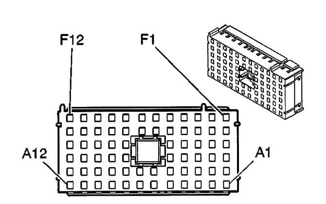
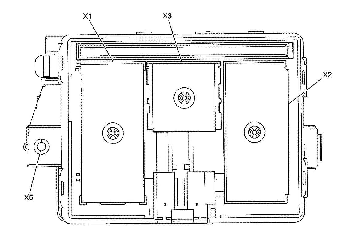
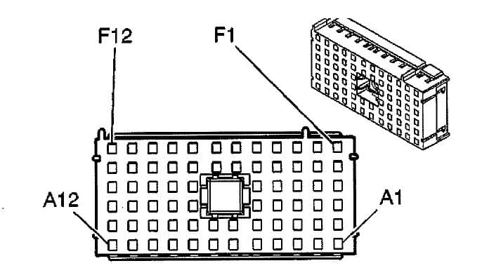
Underhood Fuse Block (Top View)
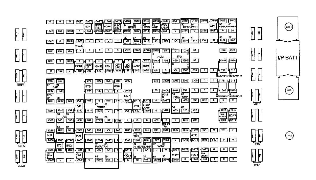
Underhood Fuse Block (Bottom View)
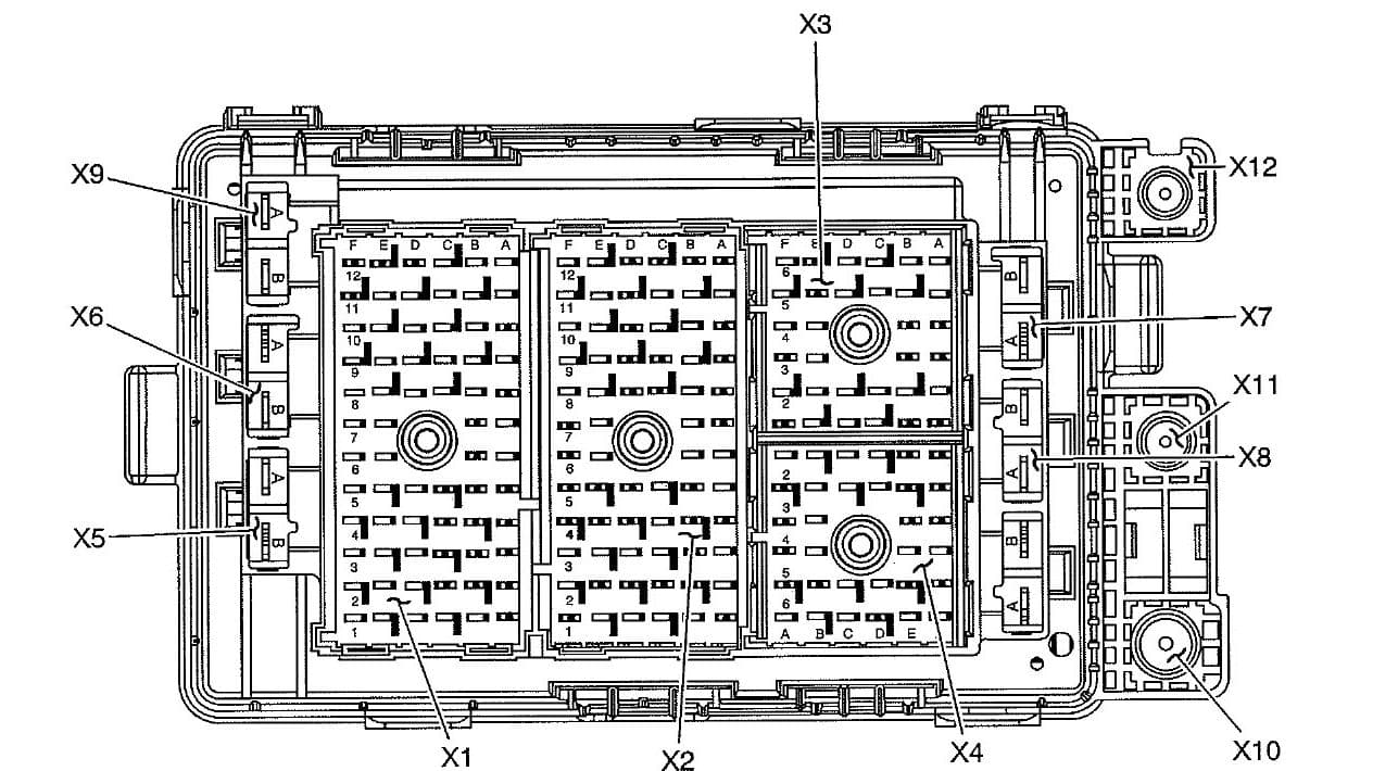
Underhood X1 Fuse block
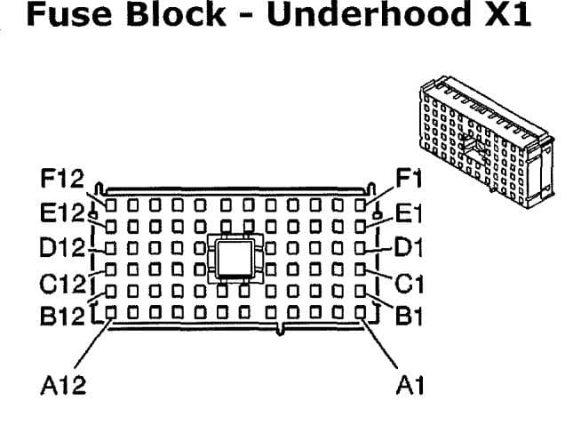
| Pin | Wire | Circuit | Function |
| A1 | — | — | — |
| A2 | — | — | — |
| A3 | — | — | — |
| A4 | — | — | — |
| A5 | 0.35 PK | 639 | lgnition 1 Voltage (M30) |
| A6 | 0.35 PU | 806 | Crank Voltage |
| A7 | 0.35 OG/BK | 463 | Requested Torque Signal |
| A8 | 5 PU | 6 | Starter Solenoid Crank Voltage |
| A9 | 0.8 GY | 1524 | Backup Lamp Signal (UY7) |
| A10 | 0.35 YE | 1737 | Neutral Safety Switch Park/Neutral Signal (M30) |
| A11 | 0.5 PK | 239 | Ignition 1 Voltage |
| 0.5 PK | 239 | Ignition 1 Voltage (6.0L) | |
| A12 | — | — | — |
| B1 | 0.35 OG | 240 | Battery Positive Voltage |
| B2 | — | — | — |
| B3 | — | — | — |
| B4 | — | — | — |
| B5 | 0.8 PK | 339 | Ignition 1 Voltage |
| B6 | 0.5 L-GN | 275 | Park Neutral Position Switch Pa rk Signal |
| B7 | — | — | — |
| B8 | 0.35 D-GN/WH | 465 | Fuel Pump Relay Control |
| B9 | 0.35WH | 1310 | EVAP Canister Vent Solenoid Control |
| B10 | 0.35 TN/8K | 464 | Delivered Torque Signal |
| B11 | 0.35 OG | 540 | Battery Positive Voltage |
| B12 | — | — | — |
| C1 | 0.8 OG | 3840 | Battery Posit ive Voltage |
| C2 | 0.5 PK | 139 | Ignition 1 Voltage |
| C3 | — | — | — |
| C4 | — | — | — |
| C5 | 0.5 PK | 439 | Ignition 1 Voltage |
| C8 | — | — | — |
| C9 | — | — | — |
| C10 | 2 BK | 550 | Ground |
| C11 | 0.8 PK | 1339 | Ignition 1 Voltage |
| C12 | — | — | — |
| D1 | 0.35 YE | 5991 | Powertrain Relay Coil Cont rol |
| D2 | — | — | — |
| D3 | 0.35 BK | 350 | Ground |
| D4 | 0.35 WH/BK | 2366 | Cooling Fan Clutch Control |
| D5 | — | — | — |
| D8 | 0.35 YE/BK | 625 | Starter Enable Relay Control |
| D9 | 0.35 D-GN/WH | 459 | A/C Compressor Clutch Relay Control |
| D10 | 0.8 BK | 550 | Ground |
| D11 | 0.35 D-GN | 59 | A/C Compressor Clutch Supply Voltage |
| D12 | — | — | — |
| E1 | 0.5 PK | 839 | Ignition 1 Voltage |
| E2 | — | — | — |
| E3 | — | — | — |
| E4 | — | — | — |
| E5 | — | — | — |
| E6 | 1 BK | 450 | Ground |
| E7 | 0.35 BK | 450 | Ground |
| 0.5 BK | 450 | Ground (M30 | |
| E8 | — | — | — |
| E9 | — | — | — |
| E10 | — | — | — |
| E11 | — | — | — |
| E12 | — | — | — |
| F1 | — | — | — |
| F2 | — | — | — |
| F3 | 1 BK | 350 | Ground |
| F4 | — | — | — |
| F5 | — | — | — |
| F6 | — | — | — |
| F7 | — | — | — |
| F8 | — | — | — |
| F9 | 0.5 PK | 539 | Ignition 1 Voltage |
| 0.5 PK | 539 | Ignition 1 Voltage | |
| F10 | 0.5 PK | 1539 | Ignition 1 Voltage |
| 0.5 PK | 1539 | Ignition 1 Voltage | |
| F11 | 0.8 PK | 1239 | Ignition 1 Voltage |
| 0.8 PK | 1239 | Ignition 1 Voltage | |
| F12 | — | — | — |
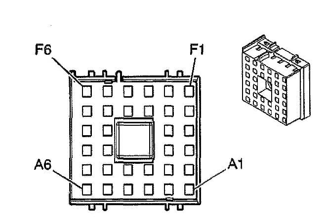
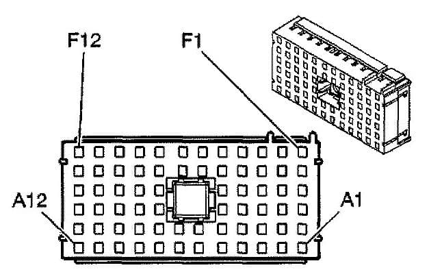
Underhood X2 Fuse block
| Pin | Wire | Circuit | Function |
| A1 | — | — | — |
| A2 | 0.5 D-GN | 189 | Headlamp Leveling Motor Supply Voltage (TR6) |
| A3 | 0.35 OG | 57 | Left Cornering Lamp Supply Voltage (Z88/Z89/W49) |
| A4 | — | — | — |
| A5 | 0.35WH/BK | 2366 | Cooling Fan Clutch Control ( 4.2L) |
| A6 | 0.35 BN | 2309 | Front Park Lamps Supply Voltage |
| A7 | 0.8 OG | 440 | Battery Positive Voltage ( 4.2L) |
| A8 | — | — | — |
| A9 | — | — | — |
| A10 | 0.8 YE | 18 | Left Rear Stop/Turn Lamp Supply Voltage (UY7) |
| A11 | 2 OG | 1640 | Battery Positive Voltage (NP4/NP8) |
| A12 | 0.35 OG | 2268 | Windshield Washer Relay Control |
| B1 | 0.35 D-BU | 2115 | Right Turn Signal Lamps Supply Voltage |
| B2 | — | — | — |
| B3 | 0.35 PK/WH | 1970 | Headlamp Low Beam Relay Control |
| B4 | — | — | — |
| B5 | — | — | — |
| B6 | 0.35 PK | 639 | Ignition 1 Voltage |
| B7 | 0.35 BK | 58 | Right Cornering Lamp Supply Voltage (Z88/Z89/W49) |
| B8 | — | — | — |
| B9 | — | — | — |
| B10 | 0.35 PU | 420 | TCC Brake Switch/Cruise Control Release Signal |
| B11 | 0.5 BN | 241 | Ignition 3 Voltage |
| B12 | — | — | — |
| C1 | 0.35 L-BU | 2114 | Left Turn Signal Lamps Supply Voltage |
| C2 | 0.35 D-GN/WH | 1317 | Front Fog Lamp Relay and Indicator Control (T96) |
| C3 | 0.35 L-GN | 2270 | Rear Window Washer Relay Control |
| C4 | — | — | — |
| C5 | — | — | — |
| C8 | — | — | — |
| C9 | 1 OG | 1540 | Battery Positive Voltage |
| C10 | 0.35 YE | 5991 | Powertrain Relay Coil Control ( 4.2L) |
| C11 | — | — | — |
| C12 | 0.35 BK/WH | 1969 | Headlamp High Beam Relay Control |
| D1 | 0.35 D-GN/WH | 1317 | Front Fog Lamp Relay and Indicator Control (T96) |
| D2 | — | — | — |
| D3 | 0.35WH | 2282 | Headlamp Washer Relay Control (CE4) |
| D4 | — | — | — |
| D5 | 2 OG | 140 | Battery Positive Voltage |
| D8 | — | — | — |
| D9 | 0.8 OG | 640 | Battery Positive Voltage |
| D10 | 0.8 D-GN | 19 | Right Rear Stop/Turn Lamp Supply Voltage (UY7) |
| D11 | — | — | — |
| D12 | — | — | — |
| E1 | 0.35 OG | 2340 | Battery Positive Voltage |
| E2 | 0.35 BK | 28 | Horn Relay Control |
| E3 | 0.35 PK | 1020 | Ignition 0 Voltage ( 4.2L) |
| E4 | — | — | — |
| E5 | 0.35 PK | 39 | Ignition 1 Voltage |
| E6 | 0.5 OG | 3240 | Battery Positive Voltage (JF4) |
| E7 | 0.5 OG | 3040 | Battery Positive Voltage (JF4) |
| E8 | — | — | — |
| E9 | — | — | — |
| E10 | 0.35 L-GN/BK | 584 | A/T Shift Lock Control Switch Supply Voltage ( 4.2L) |
| E11 | 0.5 BK/WH | 1695 | Axle Switch Signal (NP8) |
| E12 | 0.35 OG | 1140 | Battery Positive Voltage |
| 0.35 OG | 1140 | Battery Positive Voltage (BAE) | |
| F1 | 3 OG | 2940 | Battery Positive Voltage (UY7) |
| F2 | — | — | — |
| F3 | — | — | — |
| F4 | — | — | — |
| F5 | 0.35 YE | 1139 | Ignition 1 Voltage |
| F6 | 0.35 PU | 806 | Crank Voltage ( 4.2L) |
| F7 | 3 YE | 5 | Crank Voltage |
| F8 | 0.35 L-GN/BK | 584 | A/T Shift Lock Control Switch Supply Voltage (5.3L/6.0L) |
| 0.35 YE/BK | 625 | Starter Enable Relay Control ( 4. 2L) | |
| F9 | — | — | — |
| F10 | 0.35 D-GN | 1433 | PNP/Ciutch Start Switch Signal (4.2L) |
| 0.35 OG/BK | 1786 | Park/Neutral Signal (5.3L/6.0L) | |
| F11 | 3 RD | 142 | Battery Positive Voltage |
| F12 | o.35 D-GN/WH | 459 | A/C Compressor Clutch Relay Control (4. 2L) |
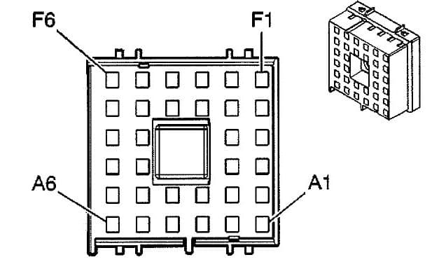
Underhood X3 Fuse block
| Pin | Wire | Circuit | Function |
| A1 | — | — | — |
| A2 | 0.5 PK | 739 | Ignition 1 Voltage ( 4.2L w/K18) |
| 0.35 PK | 739 | Ignition 1 Voltage (w/BAE) | |
| A3 | 3 OG | 2840 | Battery Positive Voltage (G67) |
| A4 | — | — | — |
| A5 | 0.35 OG | 540 | Battery Positive Voltage |
| A6 | — | — | — |
| B1 | — | — | — |
| B2 | — | — | — |
| B3 | — | — | — |
| B4 | 0.8 L-GN | 1624 | Trailer Backup Lamps Supply Voltage (UY7) |
| B5 | 0.35 BN | 441 | Ignition 3 Voltage |
| B6 | — | — | — |
| C1 | — | — | — |
| C2 | — | — | — |
| C5 | — | — | — |
| C6 | 0.35 OG | 540 | Battery Positive Voltage (5.3L) |
| D1 | — | — | — |
| D2 | 0.8 YE | 1618 | Trailer Left Rear Turn/Stop Lamp Supply Voltage (UY7) |
| D5 | 0.35 TN/BK | 464 | Delivered Torque Signal |
| D6 | 0.5 BK/WH | 1695 | Axle Switch Signal (NP8) |
| E1 | — | — | — |
| E2 | — | — | — |
| E3 | 0.35 PU | 420 | TCC Brake Switch Signal |
| E4 | 0.5 BN | 241 | Ignition 3 Voltage (NP8) |
| 0.5 BN | 241 | IIIgnition 3 Voltage (G67) | |
| E5 | 2 OG | 1640 | Battery Positive Voltage (NP8) |
| E6 | — | — | — |
| F1 | 0.5 BK | 350 | Ground |
| 0.5 BK | 350 | Ground (NP8) | |
| F2 | 0.35 OG/BK | 463 | Requested Torque Signal |
| F3 | 0.8 GY | 120 | Fuel Pump Supply Voltage |
| F4 | 0.35 WH | 1310 | EVAP Canister Vent Solenoid Control |
| F5 | — | — | — |
| F6 | 0.8 D-GN | 1617 | Trailer Right Rear Turn/Stop Lamp Supply Voltage (UY7) |
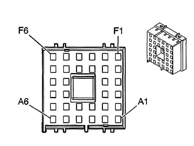
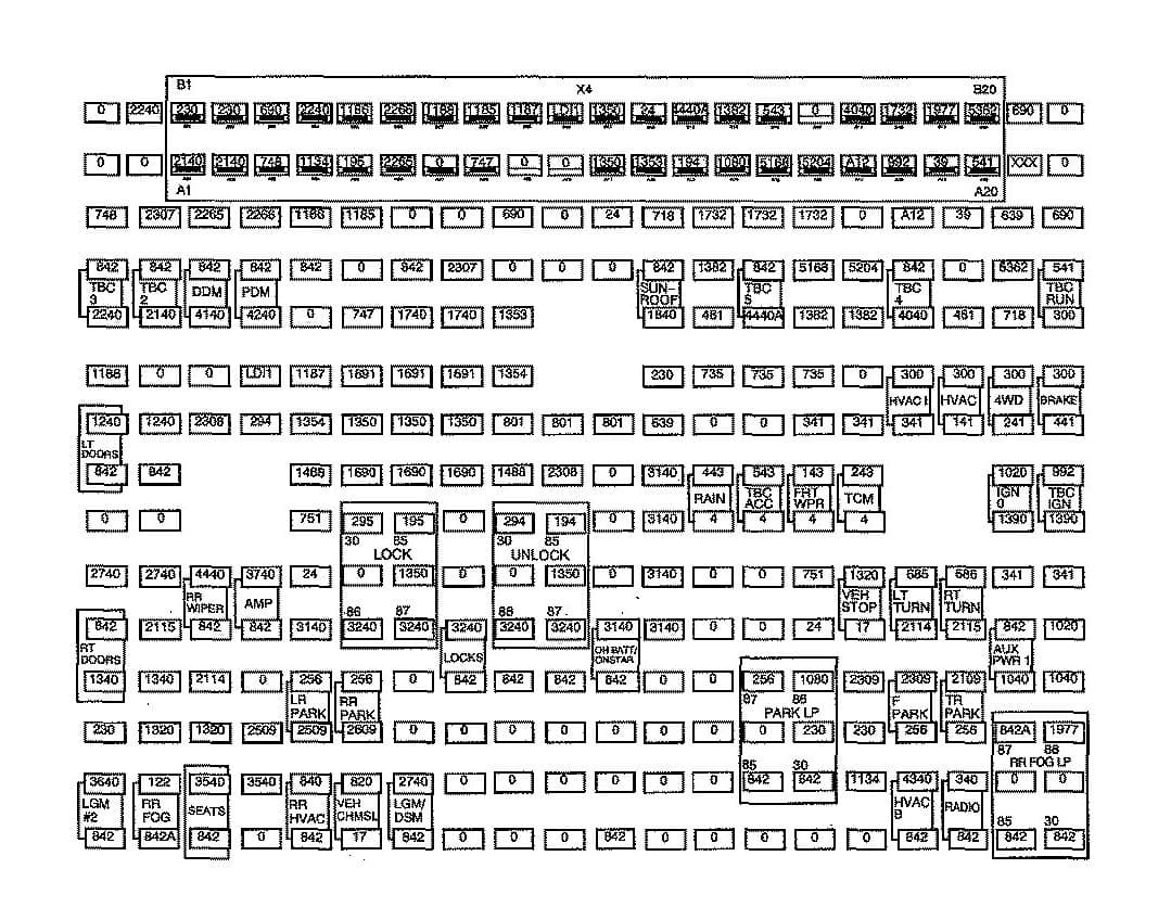
Underhood X4 Fuse block
| Pin | Wire | Circuit | Function |
| A1 | 0.35 BN | 2309 | Front Park Lamps Supply Voitage |
| 0.35 BN | 2309 | Front Park Lamps Supply Voltage (Except W49 w/o WX7) | |
| A2 | — | — | — |
| A3 | 0.35WH | 2368 | Cooling Fan Clutch Supply Voltage |
| A4 | — | — | — |
| A5 | — | — | — |
| A6 | 0.35 L-BU | 2114 | Left Turn Signal Lamps Supply Voltage |
| 0.35 L-BU | 2114 | Left Turn Signal Lamps Supply Voltage ( -WX7) | |
| B1 | 0.35 BN | 2309 | Front Park Lamps Supply Voltage |
| 0.35 BN | 2309 | Front Park Lamps Supply Voltage (Except W49 w/o WX7) | |
| B2 | 0.35 PK | 639 | Ignition 1 Voltage (TR6) |
| B3 | 0.35 BK | 639 | Ignition 1 Voltage (TR6) |
| B4 | 0.35 OG | 57 | Left Cornering Lamp Supply Voltage (Z88/W49) |
| B5 | 0.8 D-GN | 392 | Rear Window Washer Pump Control |
| B6 | — | — | — |
| C1 | — | — | — |
| C2 | — | — | — |
| C5 | 0.8 BK | 350 | Ground |
| C6 | 0.35 D-8U | 2115 | Right Turn Signal Lamps Supply Voltage |
| 0.35 D-8U | 2115 | Right Turn Signal Lamps Supply Voltage ( -WX7) | |
| D1 | — | — | — |
| D2 | — | — | — |
| D5 | 0.5 D-GN | 189 | Headlamp Leveling Motor Supply Voltage (TR6) |
| D6 | — | — | — |
| E1 | 0.35 D-GN/WH | 711 | Left Headlamp High Beam Supply Voltage |
| E2 | 0.35 YE | 712 | Left Headlamp Low Beam Supply Voltage |
| E3 | — | — | — |
| E4 | 0.5 RD | 228 | Windshield Washer Pump Control |
| E5 | — | — | — |
| E6 | — | — | — |
| F1 | 0.35 L-GN/BK | 311 | Right Headlamp High Beam Supply Voltage |
| F2 | 0.35 TN/WH | 312 | Right Headlamp Low Beam Supply Voltage |
| F3 | — | — | — |
| F4 | 0.5 D-GN | 1329 | Horn Fuse Supply Voltage |
| F5 | 0.8 PU | 1197 | Headlamp Washer Pump Control (CE4) |
| F6 | 0.8 PU | 34 | Fog Lamps Supply Voltage (T96) |
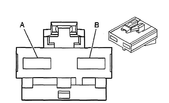
Underhood X5 Fuse block
| Pin | Wire | Circuit | Function |
| A | 3 RD/WH | 342 | Battery Positive Voltage |
| B | 3 PK | 3 | Ignition 1 Voltage |
Underhood X7 Fuse block
| Pin | Wire | Circuit | Function |
| A | 5 RD | 1042 | Battery Positive Voltage ( 4.2L w/K18) |
| B | 5 RD | 642 | Battery Positive Voltage |
Underhood X8 Fuse block
| Pin | Wire | Circuit | Function |
| A | — | — | — |
| B | 5 RD | 4042 | Battery Positive Voltage |
Underhood X9 Fuse block
| Pin | Wire | Circuit | Function |
| A | 5 RD | 542 | Battery Positive Voltage (CJ3) |
| A | 3 RD | 542 | Battery Positive Voltage (CJ2) |
| B | — | — | — |
Underhood X10 Fuse block (Battery Positive Cable)
| Pin | Wire | Circuit | Function |
| 1 | 19 RD | 1 | Battery Positive Voltage |
Rear Fuse Block
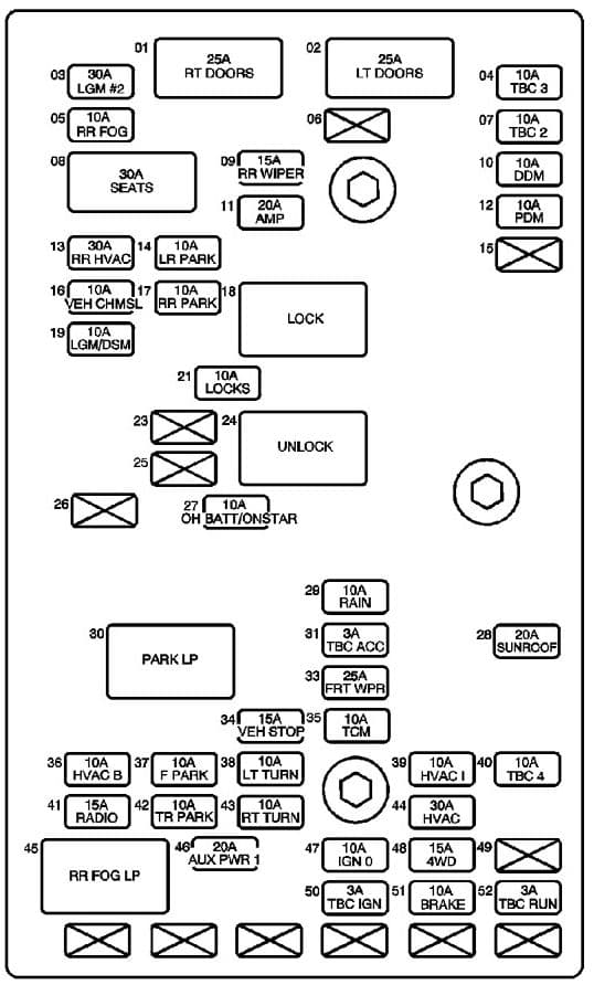
| No | Fuse name | A | Description |
| 1 | RT DOORS Circuit Breaker | 25 | Front Passenger Door Module (FPDM), Window Switch- RR |
| 2 | LT DOORS Circuit Breaker | 25 | Driver Door Module (DDM), Window Switch – LR |
| 3 | LGM #2 Fuse | 30 | Liftgate Module (LGM) |
| 4 | TBC 3 Fuse | 10 | Body Control Module (BCM) |
| 5 | RR FOG Fuse | 10 | Tail Lamp Circuit Board -Left |
| 6 | — | — | — |
| 7 | TBC 2 Fuse | 10 | Body Control Module (BCM) |
| 8 | SEATS Circuit Breaker | 30 | Lumbar Adjuster Switches, Memory Seat Module – Driver, Seat Adjuster Switches |
| 9 | RR WIPER Circuit Breaker | 15 | Rear Window Wiper Motor |
| 10 | DDM Fuse | 10 | Driver Door Module (DDM) |
| 11 | AMP Fuse | 20 | Audio Amplifier |
| 12 | PDM Fuse | 20 | Front Passenger Door Module (FPDM) |
| 13 | RR HVAC FUSE | 30 | — |
| 14 | LR PARK Fuse | 10 | License Lamps, Tail Lamp Circuit Board- Left |
| 15 | — | — | — |
| 16 | VEH CHMSL Fuse | 10 | Center High Mounted Stop Lamp (CHMSL) |
| 17 | RR PARK Fuse | 10 | Clearance Lamps, Tail Lamp Circuit Board – Right |
| 18 | LOCK Relay | — | Rear Door Latch Assemblies |
| 19 | LGM/DSM Fuse | 10 | Cobra Intrusion Sensor Module, Inclination Sensor, Liftgate Module (LGM), Memory Seat Module- Driver |
| 21 | LOCKS Fuse | 10 | LOCK Relay, UNLOCK Relay |
| 23 | — | — | — |
| 24 | UNLOCK Relay | — | Rear Door Latch Assemblies |
| 25 | — | — | — |
| 26 | — | — | — |
| 27 | OH BATT/ONSTAR Fuse | 10 | Digital Video Disc (DVD) Player, Garage Door Opener, Vehicle Communication Interface Module (CIM) |
| 28 | SUNROOF Fuse | 20 | Sunroof Motor |
| 29 | RAIN Fuse | 10 | — |
| 30 | PARK LP Relay | — | F PARK Fuse, LR PARK Fuse. RR PARK Fuse, TR PARK Fuse |
| 31 | TBC ACC Fuse | 3 | Body Control Module (BCM) |
| 32 | TBC 5 Fuse | 10 | Body Control Module (BCM) |
| 33 | FRT WPR Fuse | 25 | Windshield Wiper Motor |
| 34 | VEH STOP Fuse | 15 | Engine Control Module (ECM), Powertrain Control Module (PCM), Tail Lamp Circuit Board -Left/Right, Trailer Brake Wiring, Transmission Control Module (TCM) |
| 35 | TCM Fuse | 10 | Transmission Control Module (TCM) |
| 36 | HVAC B Fuse | 10 | HVAC Control Module, HVAC Control Module -Auxiliary |
| 37 | F PARK Fuse | 10 | Marker Lamps, Park Lamps, Park/Turn Signal Lamps, Turn Signal/Multifunction Switch |
| 38 | LT TURN Fuse | 10 | Driver Door Module (DDM), Instrument Panel Cluster (I PC), Marker Lamp, Park/Turn Signal Lamp- LF, Tail Lamp Circuit Board- Left, Turn Signal Lamp – LF |
| 39 | HVAC I Fuse | 10 | Air Temperature Actuators, Console Mode Actuator- Auxiliary, Defrost Actuator, HVAC Control Module, HVAC Control Module- Auxiliary, Mode Actuator, Recirculation Actuator, Steering Wheel Speed/Position Sensor, Turn Signal/Multifunction Switch |
| 40 | TBC 4 Fuse | 10 | Body Control Module (BCM) |
| 41 | RADIO Fuse | 15 | Digital Radio Receiver, Radio |
| 42 | TR PARK Fuse | 10 | Trailer Connector |
| 43 | RT TURN Fuse | 10 | Front Passenger Door Module (FPDM), Instrument Panel Cluster (I PC), Marker Lamp- RF, Park/Turn Signal Lamp- RF, Tail Lamp Circuit Board- Right, Turn Signal Lamp- RF |
| 44 | HVAC Fuse | 30 | HVAC Control Module |
| 45 | RR FOG LP Relay | — | RR FOG Fuse |
| 46 | AUX PWR 1 Fuse | 20 | Auxiliary Power Outlets |
| 47 | IGN 0 Fuse | 10 | Automatic Transmission, Automatic Transmission Shift Lock Actuator, Engine Control Module (ECM). Powertrain Control Module (PCM), Theft Deterrent Control Module |
| 48 | 4WD Fuse | 15 | Air Suspension Compressor Assembly, Auxiliary Water Pump Relay 1, Front Axle Actuator, Transfer Case Shift Control Switch |
| 49 | — | — | — |
| 50 | TBC IG Fuse | 3 | Body Control Module (BCM) |
| 51 | BRAKE Fuse | 10 | Electronic Brake Control Module (EBCM) |
| 52 | TBC RUN Fuse | 3 | Body Control Module (BCM) |
Rear fuse block (Top View)
Rear fuse block (Bottom View)
Rear fuse block X1
| Pin | Wire | Circuit | Function |
| A1 | — | — | — |
| A2 | 0.35 BN/WH | 230 | Instrument Panel Lamps Dimming Control |
| A3 | — | — | — |
| A4 | 0.35 L-GN | 24 | Backup Lamp Supply Voltage (Z88) |
| A5 | — | — | — |
| A6 | 3 BN | 4 | Accessory Voltage |
| A7 | 1 YE | 143 | Accessory Voltage |
| A8 | 0.35 BN | 341 | Ignition 3 Voltage |
| A9 | 0. 35 L-G N/BK | 735 | Ambient Air Temperature Sensor Signal (CJ3) |
| A10 | — | — | — |
| A11 | 0.35 TN/BK | 5168 | Power Sounder Enable Signal (BAE) |
| A12 | — | — | — |
| B1 | 0.35 L-BU | 1134 | Park Brake Switch Signal |
| B2 | 0.35 BN/WH | 230 | Instrument Panel Lamps Dimming Control |
| B3 | 0.35 BN | 2309 | Front Park Lamps Supply Voltage (Z88/Z89/W49) |
| B4 | 1 WH | 17 | Stop Lamp Switch Signal |
| B5 | 0.35 L-BU | 1320 | Stop Lamp Supply Voltage |
| 0.5 L-BU | 1320 | Stop Lamp Supply Voltage (UY7) | |
| B6 | — | — | — |
| B7 | 0.35 YE | 243 | Accessory Voltage (5.3L/6.0L) |
| B8 | 0.35 BN | 341 | Ignition 3 Voltage |
| B9 | — | — | — |
| B10 | 0.35 PU/WH | 1382 | LED Dimming Signal |
| 0.35 PU/WH | 1382 | LED Dimming Signal (NP8) | |
| B11 | 0.35 BN | 5204 | Intrusion Sensor Data Signal (8AE) |
| B12 | — | — | — |
| C1 | 0.35 OG | 4340 | Battery Positive Voltage |
| 0.35 OG | 4340 | Battery Positive Voltage (CJ2) | |
| C2 | — | — | — |
| C3 | 0.35 BN | 2309 | Front Park Lamps Supply Voltage |
| C4 | 0.35 L-BU | 2114 | Left Turn Signal Lamps Supply Voltage |
| C5 | 0.35 YE | 685 | Left Turn Signal Flasher Signal |
| C8 | 0.35 BN | 341 | Ignition 3 Voltage |
| C9 | — | — | — |
| C10 | — | — | — |
| C11 | — | — | — |
| C12 | — | — | — |
| D1 | 0.5 OG | 340 | Battery Positive Voltage |
| 0.5 OG | 340 | Battery Positive Voltage (U2K) | |
| D2 | — | — | — |
| D3 | 0.8 BN | 2109 | Trailer Park Lamps Supply Voltage (UY7) |
| D4 | 0.35 D-BU | 2115 | Right Turn Signal Lamps Supply Voltage |
| D5 | 0.35 TN | 686 | Right Turn Signal Flasher Signal |
| D8 | 3 BN | 141 | Ignition 3 Voltage (CJ3) |
| D9 | 3 OG | 300 | Ignition 3 Voltage |
| D10 | — | — | — |
| D11 | — | — | — |
| D12 | 0.35 PK | 39 | Ignition 1 Voltage |
| E1 | — | — | — |
| E2 | — | — | — |
| E3 | 1 OG | 1040 | Battery Positive Voltage |
| E4 | — | — | — |
| E5 | 0.35 BN | 341 | Ignition 3 Voltage |
| E6 | 3 WH | 1390 | Off/Run/Crank Voltage |
| E7 | 0.35 PK | 1020 | Ignition 0 Voltage |
| E8 | 0.5 BN | 241 | Ignition 3 Voltage |
| 0.5 BN | 241 | Ignition 3 Voltage (NP8/NR9) | |
| E9 | — | — | — |
| E10 | 0.35 BN | 718 | Low Reference (CJ3) |
| E11 | 0.35 L-BU | 5362 | Inclination Sensor Signal (BAE) |
| E12 | 0.35 PK | 639 | Ignition 1 Voltage |
| F1 | — | — | — |
| F2 | 0.35 YE | 1799 | Rear Fog Lamp Relay and Indicator Control (T79) |
| F3 | 1 OG | 1040 | Battery Positive Voltage |
| F4 | 0.35 PK | 1020 | Battery Positive Voltage (BAE) |
| F5 | 0.35 BN | 341 | Ignition 3 Voltage (JL4) |
| F6 | — | — | — |
| F7 | — | — | — |
| F8 | 0.35 BN | 441 | Ignition 3 Voltage |
| F9 | — | — | — |
| F10 | — | — | — |
| F11 | — | — | — |
| F12 | — | — | — |
Rear fuse block X2
| Pin | Wire | Circuit | Function |
| A1 | 2 OG | 3640 | Battery Positive Voltage |
| A2 | — | — | — |
| A3 | 2 OG | 1340 | Battery Positive Voltage |
| A4 | — | — | — |
| A5 | 0.35 OG | 2740 | Battery Positive Voltage (w/Memory) |
| A6 | — | — | — |
| A7 | — | — | — |
| A8 | 2 OG | 1240 | Battery Positive Voltage |
| A9 | 0.35 D-GN | 1188 | Power Window Switch Right Rear Down Signal |
| A10 | — | — | — |
| A11 | — | — | — |
| A12 | 0.35 L-GN/BK | 748 | Right Rear Door Ajar Switch Signal |
| B1 | 0.35 RD | 122 | Rear Fog Lamp Supply Voltage (T79) |
| B2 | 0.5 L-BU | 1320 | Stop Lamp Supply Voltage |
| B3 | 2 OG | 1340 | Battery Positive Voltage |
| B4 | 0.35 D-BU | 2115 | Right Turn Signal Lamps Supply Voltage |
| B5 | 0.35 OG | 2740 | Battery Positive Voltage |
| B6 | — | — | — |
| B7 | — | — | — |
| B8 | 2 OG | 1240 | Battery Positive Voltage |
| B9 | — | — | — |
| B10 | — | — | — |
| B11 | — | — | — |
| B12 | 0.35 D-BU | 2307 | Passenger Air Bag On Indicator Control (w/ALO) |
| C1 | 3 OG | 3540 | Battery Positive Voltage (AR9) |
| C2 | 0.5 L-BU | 1320 | Stop Lamp Supply Voltage |
| C3 | 0.35 L-BU | 2114 | Left Turn Signal Lamps Supply Voltage |
| C4 | — | — | — |
| C5 | 1 OG | 4440 | Battery Positive Voltage |
| C8 | 0.35 D-GN | 2308 | Passenger Air Bag Off Indicator Control (w/ ALO) |
| C9 | — | — | — |
| C10 | 0.35 OG | 4140 | Battery Positive Voltage |
| C11 | — | — | — |
| C12 | 0.35 L-BU | 2265 | Power Window Lockout Left Rear Signal |
| D1 | 3 OG | 3540 | Battery Positive Voltage (AR9) |
| D2 | 0.35 BN | 2509 | Left Rear Park Lamps Supply Voltage |
| D3 | — | — | — |
| D4 | — | — | — |
| D5 | 0.8 OG | 3740 | Battery Positive Voltage (UQA) |
| D8 | 0.35 TN | 294 | Door Lock Actuator Unlock Control |
| D9 | — | — | — |
| D10 | 0.35 OG | 4240 | Battery Positive Voltage |
| D11 | — | — | — |
| D12 | 0.35 L-GN | 2266 | Power Window Lockout Right Rear Signal |
| E1 | — | — | — |
| E2 | 0.35 BN | 2509 | Left Rear Park Lamps Supply Voltage |
| E3 | — | — | — |
| E4 | 0.35 OG | 3140 | Battery Positive Voltage (UEl) |
| E5 | 0.35 L-GN | 24 | Backup Lamp Supply Voltage (X88/W49/Z89) |
| E6 | — | — | — |
| E7 | — | — | — |
| E8 | — | — | — |
| E9 | 0.35 YE | 1187 | Power Window Switch Left Rear Down Signal |
| E10 | — | — | — |
| E11 | — | — | — |
| E12 | 0.35 GY/BK | 1186 | Power Window Switch Right Rear Up Signal |
| F1 | 0.35 YE | 820 | CHMSL Supply Voltage |
| F2 | 0.35 BN/WH | 2609 | Right Rear Park Lamps Supply Voltage |
| F3 | — | — | — |
| F4 | — | — | — |
| F5 | — | — | — |
| F6 | 0.35 GY | 295 | Door Lock Actuator Lock Control |
| F7 | — | — | — |
| F8 | 1 BK | 1350 | Ground |
| F9 | — | — | — |
| F10 | 0.35 L-BU/BK | 747 | Left Rear Door Ajar Switch Signal |
| F11 | — | — | — |
| F12 | 0.35WH | 1185 | Power Window Switch Left Rear Up Signal |
Rear fuse block X3
| Pin | Wire | Circuit | Function |
| A1 | — | — | — |
| A2 | 1 BK | 1350 | Ground |
| A3 | — | — | — |
| A4 | — | — | — |
| A5 | 0.35 D-BU | 2307 | Passenger Air Bag On Indicator Cont rol (w/ ALO) |
| A6 | — | — | — |
| B1 | — | — | — |
| B2 | — | — | — |
| B3 | — | — | — |
| B4 | 0.35 D-BU | 1353 | RAP Supply Voltage (CF5) |
| B5 | — | — | — |
| B6 | 0.35 GY/BK | 690 | Courtesy Lamp Low Control |
| C1 | 0.35 D-GN | 2308 | Passenger Air Bag On Indicato·r Control (w/ ALO) |
| C2 | — | — | — |
| C5 | — | — | — |
| C6 | — | — | — |
| D1 | — | — | — |
| D2 | — | — | — |
| D5 | — | — | — |
| D8 | 0.35 L-GN | 24 | Backup Lamp Supply Voltage (DD7 /DF5) |
| E1 | 0.35 OG | 3140 | Battery Positive Voltage |
| E2 | 0.35 PK | 639 | Ignition 1 Voltage (ALO/DD7 /DF5) |
| E3 | 0.35 BN/WH | 230 | Instrument Panel Lamps Dimming Control (UG1/CF5) |
| E4 | 1 OG | 1740 | Battery Positive Voltage (CFS) |
| E5 | — | — | — |
| E6 | 0 .35 BN | 718 | Low Reference (DD7 / DF5) |
| F1 | — | — | — |
| F2 | — | — | — |
| F3 | 0.35 L-GN/BK | 735 | Ambient Air Temperature Sensor Signal (DD7 /DF5) |
| F4 | — | — | — |
| F5 | — | — | — |
| F6 | 0.35 OG | 1732 | llcourtesy Lamps Supply Voltage |
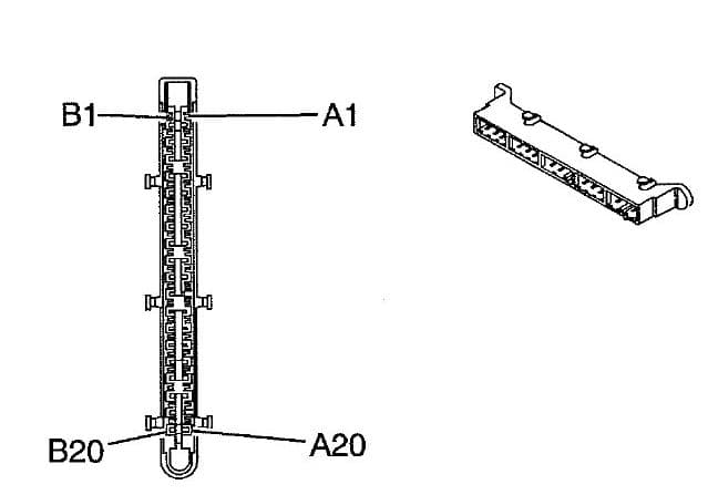
Rear fuse block X4
| Pin | Wire | Circuit | Function |
| A1 | — | 2140 | Battery Positive Voltage |
| A2 | — | 2140 | Battery Positive Voltage |
| A3 | — | 748 | Right Rear Door Ajar Switch Signal |
| A4 | — | 1134 | Park Brake Switch Signal |
| A5 | — | 195 | Door Lock Relay Control |
| A6 | — | 2265 | Power Window Lockout Left Rear Contro l |
| A7 | — | HD11 | — |
| A8 | — | 747 | Left Rear Door Ajar Switch Signal |
| A9 | — | LD14 | — |
| A10 | — | LD16 | — |
| A11 | — | 1350 | Ground |
| A12 | — | 1353 | RAP Supply Voltage |
| A13 | — | 194 | Door Unlock Relay Control |
| A14 | — | 1080 | — |
| A15 | — | LS05 | Power Sounder Enable Signal (BAE) |
| A16 | — | 1828 | Power Sounder Enable Signal (BAE) |
| A17 | — | A12 | — |
| A18 | — | 992 | Ignition o Voltage |
| A19 | — | 39 | Ignition 1 Voltage |
| A20 | — | 541 | Ignition 3 Voltage |
| B1 | — | 230 | — |
| B2 | — | 230 | — |
| B3 | — | 690 | Courtesy Lamp Supply Voltage |
| B4 | — | 2240 | Battery Positive Voltage |
| B5 | — | 1196 | Power Window Switch Right Rear Up Signal |
| B6 | — | 2266 | Power Window Lockout Right Rear Signal |
| B7 | — | 1188 | Power Window Switch Right Rear Down Signal |
| B8 | — | 1185 | Power Window Switch Left Rear Up Signal |
| B9 | — | 1187 | Power Window Switch Left Rear Down Signal |
| B10 | — | LD11 | — |
| B11 | — | 1350 | Ground |
| B12 | — | 24 | Backup Lamp Supply Voltage |
| B13 | — | 4440 | Battery Positive Voltage |
| B14 | — | 1382 | LED Dimming Signal |
| B15 | — | 543 | Accessory Voltage |
| B16 | — | HS02 | — |
| B17 | — | 4040 | Battery Positive Voltage |
| B18 | — | 1732 | Inadvertent Power Courtesy Lamps Supply Voltage |
| B19 | — | 1977 | Rear Fog Lamp Relay and Indicator Control (T79) |
| B20 | — | LS03 | Inclination Sensor Signal (BAE) |
WARNING: Terminal and harness assignments for individual connectors will vary depending on vehicle equipment level, model, and market.
Still have questions or want to supplement the article? Discuss On Telegram