 Jonathan Yarden
 Year of production: 1994, 1995, 1996, 1997, 1998, 1999, 2000, 2001, 2002
Importing this car? Don't forget to calcular iva 23%.
Right hand seat fuse box
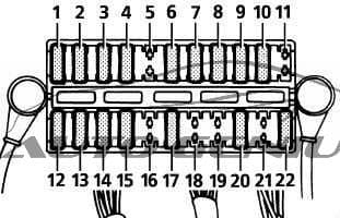
| Number | [A] | Circuit protected |
| 1 | 10 | Instrument pack, Clock, Radio, Centre console switch pack |
| 2 | 30 | RH rear window, LH/RH seat heater |
| 3 | 5 | EAT ECU – Battery supply |
| 4 | 30 | Transfer box ECU – Battery supply |
| 5 | — | Spare |
| 6 | 10 | Rear view mirror dip, Spare 1 ignition, Sun visor illumination. Up to 99MY: EAT ECU Ignition supply, Transfer box ECU ignition supply |
| 7 | 10 | Up to 99MY: Airbag From 99MY: EAT ECU Ignition supply, Transfer box ECU ignition supply |
| 8 | 30 | Car phone, radio, front cigar lighter, HEVAC. Up to 99MY: Aerial amplifier |
| 9 | 20 | LH/RH front ICE amplifier, LH/RH door Battery 2 |
| 10 | 30 | RH seat Battery 1, RH seat battery 2, RH seat lumbar, Rear cushion battery 1, Fore/aft adjustment battery 1, Front cushion battery 2, backrest battery 2, headrest battery 2 |
| 11 | — | Spare (When spare fuse of at least 5 Amps is inserted, transfer box moves to neutral position) |
| 12 | 30 | Heated rear window, LH rear window |
| 13 | 20 | Shift interlock solenoid, Sunroof Up to 99MY: Key inhibit solenoid |
| 14 | 30 | LH/RH rear central door locking, Fuel flap release, trailer battery supply |
| 15 | 20 | LH/RH rear ICE amplifiers, Courtesy/Load space lamps, ICE subwoofer RH rear courtesy lamp, RF remote receiver, Tail door central door locking, Rear wiper |
| 16 | 30 | Spare |
| 17 | 10 | Brake switch feed Up to 99MY: HEVAC ignition signal, Air suspension switches |
| 18 | 30 | 6th outstation battery supply (not fitted) |
| 19 | — | Spare |
| 20 | 30 | LH seat battery 1, LH seat battery 2, LH seat lumbar, Rear cushion battery 1, Fore/aft adjustment battery 1, Backrest battery 2, Front cushion battery 2, Headrest battery 2 |
| 21 | — | Spare |
| 22 | 30 | LH door battery 1 (front window only), RH door battery 2 (front window only) |
Engine compartment fuse box
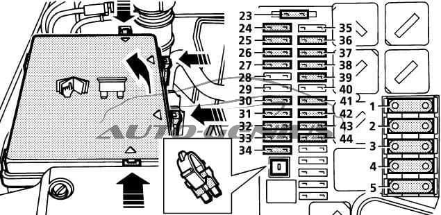
| Number | [A] | Circuit protected |
| 1 | 60 | * |
| 2 | 50 | Spare |
| 3 | 40 | ABS pump |
| 4 | 60 | * |
| 5 | 60 | * |
| 23 | 10 | Airbag SRS |
| 24 | 5 | ABS |
| 25 | 20 | Front wiper system, headlight washers |
| 26 | 20 | Engine management system (EMS) |
| 27 | 10 | Air conditioning compressor |
| 28 | 30 | Ignition coils – petrol engines |
| 15 | Cooling fan – diesel engines | |
| 29 | 10 | Air suspension |
| 30 | 30 | Heated front screen |
| 31 | 30 | Air-conditioning |
| 32 | 30 | Heated front screen |
| 33 | 5 | Diagnostics, battery back-up sounder |
| 34 | 30 | Heater blower |
| 35 | 10 | Air conditioning, air suspension |
| 36 | 30 | Air-conditioning |
| 37 | 30 | Engine management system (EMS) |
| 38 | 30 | ABS |
| 39 | 20 | Fuel pump |
| 40 | 40 | Starter motor, air suspension |
| 41 | 20 | Horn |
| 42 | 10 | Heating & ventilation, key inhibit |
| 43 | 30 | Heater blower |
| 44 | 30 | Engine management system (EMS) |
WARNING: Terminal and harness assignments for individual connectors will vary depending on vehicle equipment level, model, and market.