Year of production: 1997, 1998, 1999, 2000, 2001, 2002, 2003
Passenger compartment fuse box
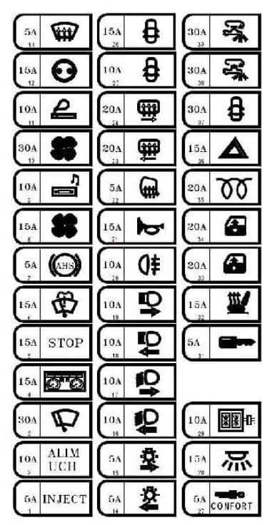
| Fuse | Ampere riting [A] | Description |
| F1 | 5 | Injection computer + after ignition feed – starter relay – gearbox computer – after ignition relay 1 – diagnostic socket |
| F2 | 10 | UCH supply – first row cigarette lighter -door locking – heated rear screen – idle speed regulator – rear fog light relay – gear selector light – air conditioning control panel – cruise control – cruise control stop switch – variable damping – headlight adjustment – heated windscreen deicing – parking proximity sensor computer -cruise control – gearbox load control – controlled suspension computer |
| F3 | 30 | Washer/wiper combination switch – UCH |
| F4 | 15 | Instrument panel – pretensioner and airbag computer – Tachograph |
| F5 | 15 | Brake switch – alternator – reversing light switch – reversing light relay |
| F6 | 15 | Washer/wiper combination switch – windscreen wiper motor |
| F7 | 5 | ABS – vehicle speed sensor |
| F8 | 15 | Air conditioning control relay – diesel heater relay – engine fuse board (position B track 4, for additional adaptations on reversal bornier (16-seater bus)) |
| F9 | 10 | Radio – multifunction display – car phone communication interface – central communication unit |
| F10 | 30 | Air conditioning control panel |
| F11 | 10 | Cigarette lighter |
| F12 | 15 | Accessories socket |
| F13 | 5 | Injection computer – reversal bornier for additional adaptations (16-seater bus) |
| F14 | 5 | Left-hand side light – left-hand rear light – multifunction display – central communication unit |
| F15 | 5 | Right-hand side light – right-hand rear light – right-hand number plate light – caravan connection – Tachograph – instrument panel |
| F16 | 10 | Left-hand dipped beam headlight – headlight adjustment control – instrument panel |
| F17 | 10 | Right-hand dipped beam headlight |
| F18 | 10 | Left-hand main beam headlight – instrument panel |
| F19 | 10 | Right-hand main beam headlight |
| F20 | 10 | Rear fog light relay – caravan connection |
| F21 | 15 | Horn |
| F22 | 5 | Heated door mirrors |
| F23 | 20 | Heated right-hand rear quarter panel |
| F24 | 20 | Heated left-hand rear quarter panel |
| F25 | 10 | 16-seater bus: Front door electric locking |
| F26 | 15 | 16-seater bus: Rear right-hand door electric locking |
| F27 | 5 | except 16-seater bus: Controlled suspension computer |
| F28 | 15 | Tachograph – instrument panel – alarm siren – diagnostic socket – alarm sensor UCH |
| F29 | 10 | Radio – multifunction display – car phone communication interface – central communication unit |
| F30 | — | — |
| F31 | 5 | Impact sensor – UCH |
| F32 | 15 | Heated front seats – electric door mirror control |
| F33 | 20 | Driver’s control for front passenger electric window – passenger electric window control |
| F34 | 20 | Electric window timer |
| F35 | 20 | Diesel heater relay |
| F36 | 15 | except 16-seater bus: Hazard warning lights 16-seater bus: Hazard warning lights – Tachograph – instrument panel – alarm siren – diagnostic socket – alarm sensor |
| F37 | 30 | Door control |
| F38 | 30 | 16-seater bus: Consumer cut-out (fuse F36 supply) |
| F39 | 30 | Consumer cut-out (supply to fuses F27, F28, F29 and F31) |
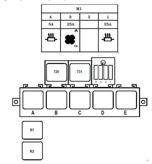
Passenger Compartment Fuse Modules (except 16-seater bus)
These modules are mounted on the passenger compartment relay board, on the left-hand dashboard fascia.
| Number | Ampere rating [A] | Description |
| F1 | 25 | 9-seater bus: + Battery feed before battery cut-off heating output |
| F2 | — | 9-seater bus: Not in use |
| F3 | 25 | 9-seater bus: Condenser relay |
| F4 | 5 | 9-seater bus: + Battery feed before battery cut-off heating control |
| Relay | ||
| A | + After ignition 1 | |
| B | — | |
| C | Passenger compartment fan assembly speed 4 | |
| D | Independent heating cut-off | |
| E | Heated rear screen and door mirrors | |
| R1 | 9-seater bus: Air conditioning + after ignition feed | |
| R2 | 9-seater bus: Condenser | |
| 720 | Air conditioning cut-off | |
| 731 | Heated windscreen | |
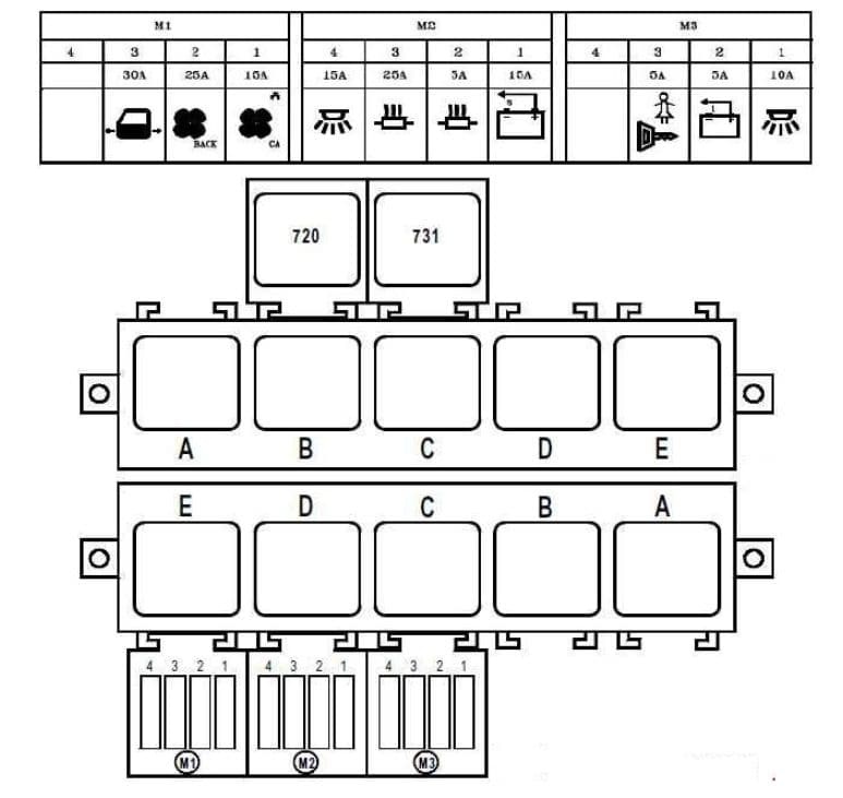
Passenger Compartment Fuse Modules (16-seater bus)
These modules are mounted on the passenger compartment relay board, on the left-hand dashboard fascia.
| Fuse | Ampere riting [A] | Description |
| Module 1 (M1) | ||
| F1 | 15 | Condenser relay |
| F2 | 25 | + After ignition relay 2 |
| F3 | 30 | Electric door power after battery cut-off |
| F4 | — | — |
| Module 2 (M2) | ||
| F1 | 15 | Battery cut-off relay |
| F2 | 5 | + Battery feed before battery cut-off heating control |
| F3 | 25 | + Battery feed before battery cut-off heating output |
| F4 | 15 | Operating light and footwell signal + battery feed after battery cut-off |
| Module 3 (M3) | ||
| F1 | 10 | + After ignition relay 2 supply (299-752) – electric doors – passenger lighting – central door locking |
| F2 | 5 | Emergency stop – switch open |
| F3 | 5 | Rear door locks + after ignition |
| F4 | — | — |
| Relay | ||
| 720 | Air conditioning cut-off | |
| Top row | ||
| A | + After ignition 1 | |
| B | Fog lights | |
| C | Passenger compartment fan assembly speed 4 | |
| D | Independent heating cut-off | |
| E | Heated rear screen and door mirrors | |
| Bottom row | ||
| A | Battery cut-out | |
| B | Battery cut-out locking | |
| C | + After ignition 2 | |
| D | Evaporator | |
| E | Condenser | |
WARNING: Terminal and harness assignments for individual connectors will vary depending on vehicle equipment level, model, and market.


