Year of production: 1997, 1998, 1999, 2000, 2001, 2002, 2003, 2004
Importing this car? Don't forget to calcular iva 23%.
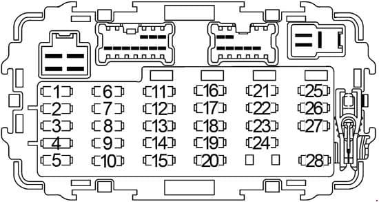
Passenger Compartment Fuse Box
| No. |
A |
Circuit Protected |
| 1 | 15 | Fuel Pump Relay |
| 2 | 7.5 | Hazad Switch |
| 3 | 10 | Injectors |
| 4 | – | – |
| 5 | 10 | ASCD Brake Switch (Shift Lock Brake Switch), Vehicle Security Relay, SECU, ASCD Control Unit, Warning Chime Unit, Rear Window Defogger Relay, Rear Window Defogger Timer, Low Tire Pressure Warning System, Daytime Light Control Unit, Overdrive Hold Control Module (KA24DE + Automatic Transmission) |
| 6 | 20 | Front Wiper Motor, Front Washer Motor, Air Control, Front Wiper Switch |
| 7 | 7.5 | Engine Control Module (ECM), Daytime Light Control Unit |
| 8 | 10 | ABS, Pressure Switch |
| 9 | 10 | Air Bag Diagnosis Sensor Unit |
| 10 | 10 | ABS |
| 11 | 10 | Combination Meter, Clutch Interlock Relay, 4WD Switch, Back-Up Lamp Switch, Transfer Neutral Position Switch, CAN Converter, Steering Wheel Angle Sensor, Compass and Thermometer, Data Link Connector |
| 12 | 10 | Park/Neutral Position Switch, Transmission Control Module (TCM) |
| 13 | 10 | Engine Control Module (ECM), EGRC Solenoid Valve, EVAP Canister Vent Control Valve, Vacuum Cut Valve Bypass Valve, Supercharger Bypass Valve Control Solenoid Valve |
| 14 | 15 | Heated Oxygen Sensor |
| 15 | 10 | IACV-AAC Valve, Throttle Position Sensor |
| 16 | – | – |
| 17 | 10 | Hazard Switch |
| 18 | 10 | Audio, Door Mirror Switch |
| 19 | 15 | Blower Motor |
| 20 | 7.5 | Low Tire Pressure Warning System, SECU |
| 21 | – | – |
| 22 | 20 | 4-Door: Stop Lamp Switch |
| 15 | 2-Door: Stop Lamp Switch | |
| 23 | 15 | Cigarette Lighter |
| 24 | 15 | Blower Motor |
| 25 | 20 | Rear Window Defogger Relay |
| 26 | 7.5 | Data Link Connector, Map Lamp, Room Lamp, Low Tire Pressure Warning System |
| 27 | 10 | Engine Control Module (ECM), ECM Relay |
| 28 | 7.5 | Combination Meter, Key Switch, Security Indicator Lamp, SECU, Transmission Control Module (TCM) |
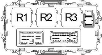
| No. |
Relay |
| R1 | Accessory |
| R2 | Blower |
| R3 | Ignition |
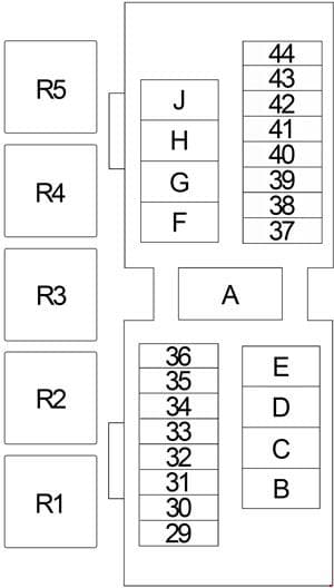
Engine Compartment Fuse Box
| No. |
A |
Circuit Protected |
| 29 | 7.5 | Air Conditioner Relay, Daytime Light Control Unit |
| 30 | – | – |
| 31 | 20 | VG33E, VG33ER: Auxiliary Power Supply |
| 32 | 15 | Horn Relay |
| 33 | 20 | VG33E, VG33ER: Audio Amplifier |
| 34 | – | – |
| 35 | 7.5 | Air Conditioner Relay |
| 36 | 7.5 | Generator |
| 37 | 15 | Headlamp RH, Lighting Switch, Daytime Light Control Unit, Vehicle Security Lamp Relay |
| 38 | 15 | Headlamp LH, Lighting Switch, Daytime Light Control Unit, Vehicle Security Lamp Relay, High Beam Indicator |
| 39 | 15 | Lighting Switch (Combination Lamps, License Plate Lamp) |
| 40 | 15 | VG33E, VG33ER: Front Fog Lamp Relay |
| 41 | 15 | ’99-’04: Audio |
| 10 | ’97-’98: Audio | |
| 42 | 20 | Front Power Socket |
| 43 | – | – |
| 44 | – | – |
| A | 80 | KA24DE: Generator, Accessory Relay (Fuse: “18”, “20”, “23”), Ignition Relay (Fuse: “2”, “5”, “6”, “8”, “10”, “11”, “12”, “15”), Blower Relay (Fuse: “19”, “24”), Fuse: “F”, “G”, “17”, “22”, “25”, “26”, “27”, “28”, “31”, “32”, “33”, “35”, “36” |
| 120 | VG33E, VG33ER: Generator, Fuse: “F”, “G”, “J”, “31”, “32”, “33”, “35”, “36” | |
| B | – | – |
| C | 40 | KA24DE: ABS |
| 30 | VG33E, VG33ER: ABS | |
| D | 40 | ABS |
| E | 40 | Ignition Switch |
| F | 30 | KA24DE: SECU, Power Window Relay |
| 40 | VG33E, VG33ER: SECU, Power Window Relay | |
| G | – | KA24DE: – |
| 20 | VG33E, VG33ER: Auxiliary Power Supply | |
| H | – | – |
| J | – | KA24DE: – |
| 80 | VG33E, VG33ER: Accessory Relay (Fuse: “18”, “20”, “23”), Ignition Relay (Fuse: “2”, “5”, “6”, “8”, “10”, “11”, “12”, “15”), Blower Relay (Fuse: “19”, “24”), Fuse: “31”, “32”, “33”, “35”, “36” | |
| Relay | ||
| R1 | VG33E, VG33ER: Front Fog Lamp | |
| R2 | VG33E, VG33ER: Vehicle Security Lamp | |
| KA24DE: Air Conditioner | ||
| R3 | VG33E, VG33ER: Air Conditioner | |
| KA24DE: Horn | ||
| R4 | VG33E, VG33ER: Horn | |
| KA24DE: Clutch Interlock (Manual Transmission) | ||
| KA24DE: Park/Neutral Position (Automatic Transmission) | ||
| R5 | VG33E, VG33ER: Clutch Interlock (Manual Transmission) | |
| VG33E, VG33ER: Park/Neutral Position (Automatic Transmission) | ||
| KA24DE: Vehicle Security Lamp | ||
WARNING: Terminal and harness assignments for individual connectors will vary depending on vehicle equipment level, model, and market.


