Year of production:
Importing this car? Don't forget to calcular iva 23%.
Location
- Fuses -S162-, -S163-, -S164-, -S176-, -S177-, -S178-, -S179-, -S180- on fuse holder/battery
- Fuses -S43-, -S111-, -S130-, -S144-, -S283-, -S329-, -S337-, -S338-, on the 13 position additional relay carrier above the relay plate
- Fuses (S) in fuse holder, left dash panel
Fuses (S) on fuse holder/battery
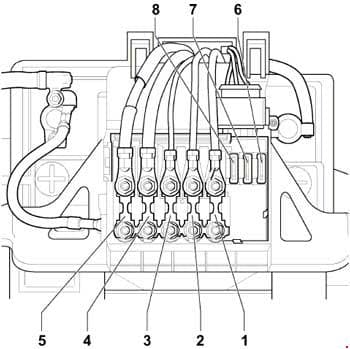
| № | A | Function/component |
| 1 | 50 | V101 – Secondary air pump motor, models with secondary air pump only J359 – Low heat output relay, models with diesel engines, manual gearbox only J360 – High heat output relay, models with diesel engines, manual gearbox only |
| 2 | 50 | J17 – Fuel pump relay (17/30) J370 – Glow plug activation control unit, models with diesel engines only |
| 3 | 40 | J293 – Radiator fan control unit (T4e/1) V7 – Radiator fan |
| 4 | 110 | J59 – X – contact relief relay (7/30) |
| 5 | 110 150 |
C – Alternator (90A) C – Alternator (120A) |
| 6 | 30 | J104 – ABS control unit (T47a/1) |
| 7 | 30 | J104 – ABS control unit (T47a/32) |
| 8 | 30 | F18 – Radiator fan thermal switch J293 – Radiator fan control unit (T4e/3) |
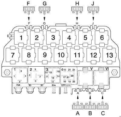
Fuses on the 13 position additional relay carrier above the relay plate
| № |
A |
Function/component |
| A | 30 | Window regulator thermal fuse -S43- |
| B | Brake vacuum pump fuse -S283-*1 Vacant*2,7 |
|
| C | 30*3 10*7 |
Rear spoiler motor fuse -S329-*3 Secondary air pump fuse -S130- |
| F | – | Vacant |
| G | – | Vacant |
| H | 15 | Anti-theft alarm system fuse and immobilizer fuse -S111-*4 Telematics fuse -S338-*5 |
| J | 15*4 20*2,6 |
Anti-theft alarm system central locking fuse -S144-*4 Brake vacuum pump fuse -S283-*2 Fuse for dual clutch gearbox mechatronic unit -S337-*6 |
| Relay positions – relay on relay plate | ||
| 1 | J4 – Dual tone horn relay (53) | |
| 2 | J59 – X-contact relief relay (100) | |
| 3 | Vacant | |
| 4 | J17 – Fuel pump relay (409) J52 – Glow plug relay (103)*8 |
|
| 5 | Automatic intermittent wash and wipe relay -J31- (377), (192), (389) | |
| Relay positions on the 13 position additional relay carrier above the relay plate | ||
| 1 | Vacant | |
| 2 | Vacant | |
| 3 | Starter inhibitor relay, clutch pedal switch -J434- (53)*9 | |
| 4 | Fog light relay -J5- (53) | |
| 5 | Vacant | |
| 6 | Vacant | |
| 7 | Daytime running lights change-over relay -J89- (173)*10 | |
| 8 | Heated exterior mirror relay -J99- (53)*11 | |
| 9 | Alarm horn relay -J641- (for telematics only) | |
| 10 | Turn signals relay for anti-theft alarm -J237- (for telematics only) Radiator fan 3rd speed relay -J135- (100) (only 1.8 l-engine) Secondary air pump relay -J299- (100) (only petrol engines, from July 2005) Low heat output relay -J359- (100) (engine code BEW only, from June 2003 up to December 2006) |
|
| 11 | Starter inhibitor and reversing light relay -J226- (126) (only for automatic gearbox 01M) Starter inhibitor relay -J207- (176) (from model year 2005; only for 6-speed automatic gearbox 09G, with Tiptronic) |
|
| 12 | Terminal 30 voltage supply relay -J317- (109) (for engine codes BPR, BPS only; models with diesel engines only) | |
| 13 | High heat output relay -J360- (53) (engine code BEW only, from June 2003 up to December 2006) | |
| 1 – for models with manual gearbox, model year 2003 2 – models with automatic gearbox, from model year 2004 3 – models with 1.8 l engine, model year 2003 up to 2005 4 – up to model year 2003 5 – from model year 2004 6 – for models with engine code BEW; with dual clutch gearbox DSG 02E; from model year 2004 7 – from model July 2005 8 – engine codes ALH, ATD, AXR, BSW only 9 – only manual gearbox 10 – daytime running lights only 11 – American markets only; only models with mechanical window regulator |
||
Fuses (S) in fuse holder, left dash panel
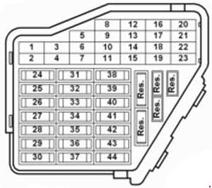
| № | A | Function/component |
| 1 | 10 | J99 – Heated exterior mirror relay*1 J131 – Heated driver seat control unit (T6/5) J132 – Heated front passenger seat control unit (T6b/5) W6 – Glove compartment light Z20/ Z21 – Left/right washer jet heater element |
| 2 | 10 | J1 – Turn signal relay (T7/6) M5/ M7 – Front left/right turn signal bulb M6/ M8 – Rear left/right turn signal bulb |
| 3 | 5 | E1 – Lighting switch E20 – Switches and instruments illumination regulator J5 – Fog light relay (4/86) |
| 4 | 5 | X – number plate light |
| 5 | 7,5 | E45 – Cruise control system switch*2 E159 – Fresh air/air recirculation flap switch (T8b/5) E184 – Fresh air and air recirculation switch*1 E227 – Cruise control system (CCS) SET button (T4q/3), CCS only*1 E231 – Exterior mirror heater button F36 – Clutch pedal switch (T4q/3) F47 – Brake pedal switch G65 – High-pressure sender (T3e/3) J89 – Daytime running lights change-over relay (8/86) J255 – Climatronic control unit (T16c/9)*1 J293 – Radiator fan control unit (T14/9) J386 – Driver door control unit (T18d/3) T16 – 16-pin connector, self-diagnosis (T16/1T16/16) V48 – Left headlight range control motor*1 V49 – Right headlight range control motor*1 Y2 – Digital clock*2 Y7 -Automatic anti-dazzle interior mirror*2 |
| 6 | 5 | J393 – Convenience system central control unit (T23/5) Vacant, model year 2004 |
| 7 | 10 | F4 – Reversing light switch F125 – Multifunction switch (T10t/10)*2 G22 – Speedometer sender J226 – Starter inhibitor and reversing light relay (T9/5) K142 – Selector lever position P/N warning lamp M16 / M17 – Left/right reversing light bulb T16 – 16-pin connector, self-diagnosis (T16/1) |
| 8 | – | Vacant J412 – Mobile telephone operating electronics control unit (T18d/10)*3 |
| 9 | 5 | E256 – TCS and ESP button (T6/6) J104 – ABS control unit (T47a/4) G85 – Steering angle sender (T6k/5) |
| 10 | 10 | J285 – Control unit in dash panel insert (T32/30) J393 – Convenience system central control unit (T23/17), models with window regulator from 2003 only R – Radio Y2 – Digital clock |
| 11 | 5 | J285 – Control unit in dash panel insert (T32/1) N110 – Selector lever lock solenoid |
| 12 | 7,5 | T16 – 16-pin connector, self-diagnosis (T16/16) J502 – Tyre pressure monitor control unit (T20b/3)*2 |
| 13 | 10 | F – Brake light switch |
| 14 | 10 | J220 – Motronic control unit (T121/62) J271 – Motronic current supply relay J393 – Convenience system central control unit (T23/22), models with window regulator from model year 2003 |
| 15 | 5 | G85 – Steering angle sender (T6p/4) for TCS/ESP J217 – Automatic gearbox control unit (T68/45) J285 – Control unit in dash panel insert (T32/23) Y2 – Digital clock*2 |
| 16 | 10 | J293 – Radiator fan control unit (T14/4) |
| 17 | – | Vacant |
| 18 | 10 | J5 – Fog light relay J285 – Control unit in dash panel insert (T32/a17) J607 – Right dip and main beam switch relay (for gas discharge bulb)*1 M32 – Right main beam bulb |
| 19 | 10 | J606 – Left dip and main beam switch relay (for gas discharge bulb)*1 M30 – Left main beam bulb |
| 20 | 15 | J607 – Right dip and main beam switch relay (for gas discharge bulb)*1 M31 – Right headlight dipped beam bulb |
| 21 | 15 | J606 – Left dip and main beam switch relay (for gas discharge bulb)*1 M29 – Left headlight dipped beam bulb |
| 22 | 5 | J285 – Control unit in dash panel insert (T32/26) M3 – Right side light bulb*2 M22 – Right brake and tail light bulb M34 – Front right side marker bulb*2 M36 – Front right turn signal and side marker bulb M38 – Rear right side marker bulb |
| 23 | 5 | J285 – Control unit in dash panel insert (T32/27) M1 – Left side light bulb*2 M21 – Left brake and tail light bulb M33 – Front left side marker bulb*2 M35 – Front left turn signal and side marker bulb M37 – Rear left side marker bulb |
| 24 | 20 | E22 – Intermittent wiper switch (T8c/8) J31 – Automatic intermittent wash and wipe relay (T18a/13), for headlight washer system only |
| 25 | 25 | E9 – Fresh air blower switch (T6d/2) J255 – Climatronic control unit (T16b/14)*1 V2 – Fresh air blower, for Climatronic only*1 |
| 26 | 25 | E15 – Heated rear window switch (T6b/5) Z1 – Heated rear window |
| 27 | 15 | U1 – Cigarette lighter, from model year 2007 J29 – Blocking diode, from model year 2007 U18 – 12 V socket -2- U19 – 12 V socket 3, in luggage compartment |
| 28 | 15 | G6 – Fuel system pressurisation pump J17 – Fuel pump relay (T9b/1)*3 |
| 29 | 15 | J220 – Motronic control unit (T121/3) J248 – Diesel direct injection system control unit (T121/37)*1 N30/ N31/ N32/ N33/ N83 – Injector, cylinder*2 J623 – Engine control unit (T80/4), engine code CBPA only*2 G70 – Air mass meter, (T5d/2), engine code BEW only, from June 2003 up to December 2006 J248 – Diesel direct injection system control unit, (T94/18), engine code BEW only, from June 2003 up to December 2006 |
| 30 | 20 | J245 – Sliding sunroof adjustment control unit (T6l/4) |
| 31 | 20 | F125 – Multifunction switch (T8a/7)*1 J217 – Automatic gearbox control unit (T68/23) J539 – Brake servo control unit (T6k/3) |
| 32 | 30 | N30/ N31/ N32/ N33 – Injector, cylinders, engine code CBPA only N280 – Air conditioning system compressor regulating valve*2 |
| 32 | 15 | J248 – Diesel direct injection system control unit (T121/2) N146 – Metering adjuster*1 |
| 33 | 20 | Vacant |
| 34 | 10 | G40 – Hall sender, engine code BEW only, from June 2003 up to December 2006 J52 – Glow plug relay (engine codes ALH and BEW only) J299 – Secondary air pump relay (T13/9)*3 J370 – Glow plug activation control unit, (6/87), engine code BEW only, from June 2003 up to December 2006 N18 – Exhaust gas recirculation valve (engine codes ALH and BEW only) N75 – Charge pressure control solenoid valve N79 – Heater element for crankcase breather*3 N108 – Commencement of injection valve (engine codes ALH and BEW only) N239 – Variable intake manifold flap change-over valve (engine codes ALH and BEW only) N205 – Inlet camshaft control valve 1 (engine codes ALH and BEW only) N249 – Turbocharger air recirculation valve (engine codes ALH and BEW only) N345 – Exhaust gas recirculation cooler change-over valve, engine code BEW only, from June 2003 up to December 2006 S130 – Secondary air pump fuse*3 V157 – Intake manifold flap motor, engine code BEW only, from June 2003 up to December 2006 |
| 35 | 30 | U19 – 12 V socket 3, in luggage compartment U10 – Trailer socket (T13/9)*3 |
| 36 | 15 | E7 – Fog light switch (T17/2) |
| 37 | 20 | J220 – Motronic control unit (T121/62) J248 – Diesel direct injection system control unit (T121/88), engine codes ALH and BEW J271 – Motronic current supply relay (1/30) J393 – Convenience system central control unit (T23/17), models with window regulator J623 – Engine control unit (T80/15), engine code CBPA only S283 – Brake vacuum pump fuse |
| 38 | 15 | E204 – Tank filler flap remote release switch E233 – Rear lid remote release button J386 – Driver door control unit (T29/19), models with window regulator J387 – Front passenger door control unit (T29a/19), models with window regulator J393 – Convenience system central control unit (T23/22)*3 |
| 39 | 15 | E3 – Hazard warning light switch (T8d/8) |
| 40 | 20 | H1 – Horn or dual tone horn J4 – Dual tone horn relay (3/30) |
| 41 | 15 | U1 – Cigarette lighter U5 – 12 V socket U18 – 12 V socket -2-, from 07.03 U19 – 12 V socket 3, in luggage compartment, from 07.03 Vacant*3 |
| 42 | 25 | R – Radio (T8/5, T8/7) |
| 43 | 10 | G39 – Lambda probe G70/G42 – Air mass meter/ Intake air temperature sender, engine codes BPS, BPR only G108 – Lambda probe 2 G130 – Lambda probe after catalytic converter G465 – Centre Lambda probe for bank 1 catalytic converter, engine code BPR only J299 – Secondary air pump relay (4/85)*1 N80 – Activated charcoal filter system solenoid valve 1 N112-Secondary air inlet valve*1 V144 – Fuel system diagnostic pump |
| 43 | 10 | F36 – Clutch pedal switch F47-Brake pedal switch J359 – Low heat output relay J360 – High heat output relay N79-Heater element for crankcase breather |
| 44 | 15 | J131 – Heated driver seat control unit (T6/4) J132 – Heated front passenger seat control unit (T6b/4) |
| 1 – model year 2002 up to july 2005 2 – from model July 2005 3 – from model July 2009 |
||
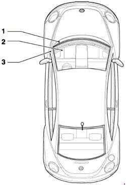
J179 – Automatic glow period control unit*¹,²
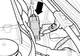
Location: in centre of plenum chamber ⇒ -arrow-
1) engine code BEW only
2) from June 2003 up to December 2006
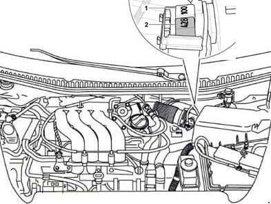
| № | Function/component |
| 1 | Secondary air pump relay -J299- (100)*1 High heat output relay -J360- (100)*2 |
| 2 | Motronic current supply relay -J271- (458)*1 Low heat output relay -J359- (53)*2 |
| 1 – petrol engines only 2 – diesel engines only |
|
WARNING: Terminal and harness assignments for individual connectors will vary depending on vehicle equipment level, model, and market.